where the key turns first.
TT |
Ok cool, thanks again for all the help :)
|
and recheck with the key in each position. (hold it in the start position whilst testin)
|
Knowing how much redundant wiring there was in gus's carb setup I expect the cfi setup will be even worse. I have got the same setup as you engine wise, but used a premier wiring loom as it is much neater than the original. Engine will run on edis alone, although it will run rough. Don't forget you will need the bike fuel pump wired in to supply the carbs with petrol.
|
Right so I tried the multimeter out on the ignition wires that connect onto where the key turns. I set it to 20 volts AC, put the black on the battery negative and the red on each wire (the loom positive connections where also connected to the battery positive). I've got a red, yellow, blue/black, and yellow black wires connecting on there. For some of the readings, it would first flash up with a number somewhere between 7 and 16 then after a second just show 1.
key position off (0) red = 1 yellow = 0.01 blue/black = 1 yellow/black = 0 key position I red=1 yellow=1 blue/black=1 yellow/black=1 key position II red=1 yellow=1 blue/black=1 yellow/black=1 |
You need to be on DC.
TT |
Opps.. Well I've redone it on DC this time and here's what I got:
Position 0 red=12.73 blue/black=12.67 yellow=0.01 yellow/black=0 Position 1 red=12.73 blue/black=12.67 yellow=12.73 yellow/black=0 Position 2 red=12.73 blue/black=12.67 yellow=12.73 yellow/black=12.73 |
All your getting is the difference in voltage drop over the different circuits. Do yourself a favour and buy one of these
http://www.uktools.com/sealey-ppx-au...4v-p-5079.html They are brilliant, put the two leads to the battery and there are two small lights which detect what you have , green which is for the earth and a red for the live, further more its got a rocker switch so if you need a live press it one way and an earth press it the other. You can then run round all the circuits testing everthing ,bulbs ,sender units, fuseboards the lot for live and earths. Bob |
Blue/black is the starter impulse wire, and should only have 12v on it when the key is in position 3. I think you have got it connected on the wrong terminal on the starter motor. There should be what looks like 3 bolts on the starter motor. The one for the impulse wire will be nearest the ground when the starter motor is fitted.
|
Quote:
|
as dave, you should only see an output on the blue/black during cranking..
Your results is odd. TT |
Ok, hopefully what dave suggested will be the case and I can fix it tonight and try starting it up :)
|
Ok so I checked the starter connections and as dave thought the red/black thin wire was on the wrong bolt (one on the top nearest to the block) so I swaped it onto the bottom one. I then re-checked the readings on the multimeter and they're the same as before, I'm still getting a 12v reading off the blue/black in all positions :( Out of curiosity I did connect the loom up to the battery negative and try checking the dash again and I do get one light coming on now (oil pressure I think?), the fuel gauge drops to zero (was previously showing full), and the water temp gauge goes up slightly by 5mm or so. Any idea's what I can try next to work out what's wrong?
 |
disconnect the solenoid wire (the thin one from the starter) and let us know the results again at the ignition switch.
TT |
Ok tried that this morning before heading off to work and as suspected I guess with the thin (black/red) wire disconnected from the starter I now get a reading of 0 volts on the blue/black wire on the ignition. So what to do next?
|
Ok, that's sort of progress. It looks like you were getting back feed from the starter motor. We need to confirm the connections on the starter motor.
TT |
Do you now get any reading on the blue/black wire whilst the key is in crank?
What are the voltages on the other wires now in each possition. The next step if you showing 0v is to do a continuity test between the ignition switch +ve terminal and the lead at the battery. TT |
CVH Starter
Here's a picture of the CVH Starter ( Original Ford unit )
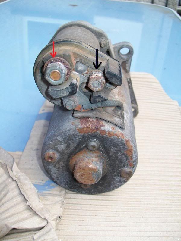 The large teminal ( Red Arrow ) Should go straight to the Positive terminal of the battery ( 12v + ) The smaller terminal ( Black Arrow ) Should go to to the ignition switch ( 12v +, switched live ) Black/Blue wire. Nothing goes to the Third terminal, other than the motors winding live feed wire from the solenoid ( Pictured ) The starter will get it's earth from a earth wire from the battery to one of the starters mounting bolts or other nearby location on the engine block. I know it won't help with the strange reading that you are getting from the ignition switch but shoud hepl to confirm if the starter is wired correctly ;) |
Yup that's definately how I wired it up, thick red onto the copper colored screw (red arrow), small red & black striped wire onto the screw you marked black (I changed this after davedew's note) and this sits closest to the floor when the starter is mounted. Also as mentioned there's a really thich black wire on the same section of the loom which I have bolted onto the gearbox. When I get home tonight I'll recheck the readings with the thin red/black striped wire disconnected. Also sorry for being a bit thick/new with this but can you explain what you mean and how to do "do a continuity test between the ignition switch +ve terminal and the lead at the battery"?
|
Set your meter to the Ohms switch (an omega sysmbol (Bit like headphones))
Set the dial to the top left setting that looks like a triangle with a line through it. also has a representation of a sound pulse ( picture is poor ) Touch the probes together and you should get a beep whilst they are connected. Dis-connect the plug from the ignition switch. Touch either probe on the positive side of the battery and whilst doing that touch the probe on each of the connections on the plug you just removed. What are the results. Also, take a wire from the small terminal on the starter motor, and touch it against the positive terminal on the battery. This should confirm the starter is working. TT |
Ok so the sound check part, that's called a continuity test? Also for the starter test, when you say the small terminal you mean the non-copper colored one that bonzo labeled with the black arrow? And then leave the thick red wire on the copper colored one? Also, would it have been feasable that my donor had something like an imobilizer fitted which is causing problems now? It looks like there was something running off the yellow/black striped wire at the ignition as this wire was cut and has a terminal block connecting it now.
|
Yes keep the big wire on.
And yes your car did have an immobaliser, you should have a black box about 2.5" x 2" x 3/4" . which needs to be bypassed if not plugged in. But we need to confirm a few things first before moving on. TT |
Right so I've done the tests again, please tell me I haven't fried my starter motor :o
First DC voltage test with the thin wire off the starter motor Position 0 Red=12.71 Blue/Black=0 Yellow=0 Yellow/Black=12.65 Position 1 Red=12.71 Blue/Black=0 Yellow=12.71 Yellow/Black=12.65 Position 2 Red=12.71 Blue/Black=0 Yellow=12.71 Yellow/Black=12.71 Position 3 Red=12.71 Blue/Black=12.71 Yellow=0 Yellow/Black=12.71 So next I did the continuity(beep) test by putting the red probe to the red battery positive, then touched the black probe into the ignition plug. Position 0 Red=beeped value 008 Blue/Black=no beep value 1 Yellow=no beep value 1 Yellow/Black=no beep value 1 Position 1 Red=beeped value 012 Blue/Black=no beep value 1 Yellow=no beep value 1 Yellow/Black=no beep value 1 Position 2 Red=beeped value 015 Blue/Black=no beep value 1 Yellow=no beep value 1 Yellow/Black=no beep value 1 Position 3 Red=beeped value 014 Blue/Black=no beep value 1 Yellow=no beep value 1 Yellow/Black=no beep value 1 Next I tried having the battery positive & negative connections on, the small red/black stripped wire off the starter leaving the thick red on the starter and the thick black earthed on the gearbox. I then took what looked like a thick black wire off the zx6r loom I have (an earth wire maybe?) and touched one side to the battery positive and then one to the bottom bolt (black arrow in bonzo's picture) and nothing happened... |
the yellow black being live all the time is odd.
I think we also need a good picture of your starter and it's connections. I would pull it off the car and get it on the bench for testing. TT |
I think the power at the ignition switch should be as follows.
Position 0 Red 12v Yellow 0v Black/Yellow 0v Black/Blue 0V Position 1 Red 12v Yellow 12v Black/Yellow 0v Black/Blue 0V Position 2 Red 12v Yellow 12v Black/Yellow 12v Black/Blue 0V Position 3 (Engine cranking) Red 12v Yellow 0v (Disabled while cranking) Black/Yellow 12v Black/Blue 12V Anything other than the above is not correct |
looks about right Dave..
TT |
So what's likely to be causing my black/yellow to be live all the time?
|
Pull fuses 20,21,22 and see if the Bl/Ye goes to 0V if it does then try removing each in sequence.
TT |
Ignition switch could be knackered, wire shorting out inside the loom, something connected incorrectly.
Got to remember loom is nearly 20 years old, has been ripped out of a car, stuffed in a box, and then laid out on your new chassis. They do get brittle. |
Quote:
BBug, we can get it running without the main harness. But we need to make sure that starter is good . TT |
Fair enough, I'm hoping the starter isn't knackered as that won't be cheap to replace :( I'll take some photos from the front and top of the starter in position tonight when I get in then take it off the block and take a few more of it on the bench closer up. I'll try the fuses too and see what happens with those. Also I need to wire up my bike fuel pump and was planning to just use terminal blocks as I can't work out how to remove the wires from the bike loom plugs and then put the sierra loom wires into that plug. The bike pump has a red and black wire, and the sierra loom connection has a brown and red/black stripped wire. Which goes to which?
|
Same with me TT. After removing all the unnecessaray parts from Gus's Sierra loom, I decided it would be easier and more reliable in the long run to fit a new loom. That's why I went for a Premier Wiring loom in the end.
|
Black/Red to the Pump Red. (Feed)
Brown to the Pump Black. (Earth) Cheers TT |
I am not sure if the bike fuel pump will work correctly wired like that. The bike pump is self regulating. ie it turns itself on and off as needed. Therefore it just needs an ignition switched power supply.
If you look at the Sierra wiring diagrams the fuel pump would have been controlled by the ecu via a relay. You are not using the Sierra ECU and therefore you will not just be able to connect the bike pump to the wires that the original pump was connected to. |
Pants so whats a good way to re-wire it? do I just trace the wire back to whatever its connected into, disconnect it, and the connect to somewhere else?
|
My personnal opinion would be to forget the fuel pump, and get the engine cranking first. Then make sure you are getting sparks. The bike pump then just needs connecting to a position 2 power feed.
Before all of this though I would remove as much of the unnecessary wiring as possible. Interior lights, stereo, door switches, immobiliser, basically anything you don't need. I removed more than I left behind from Gus's loom and he only had a carbed engine!! |
Ah right, I thought it would be best to leave stuff on for the meantime until I got it cranking/running to then make it easier to work out what I didn't need as there's alot of wires! Also long term I wanted to put a heater and stero in so would it be better to just leave those wires on the loom and hide them under the scuttle or take them off to put them back on further down the line?
|
Hmm, normally the EEC-IV ecu would power up the pump initially to prime, and then once running the ECU would keep +12V feed to the pump. Almost the same as having a ignition feed but the pump will only be running when the engine is ( safer in a crash ).
Your doing away with the ECU, so the two wires are going to be redundant(ISH). Firstly, I would make sure the inertia cutoff is incorporated in your plans. This is a black box with a red push button on the top. It needs to be mounted to a solid surface with the red button pointing upwards. Next we need to get a ignition live feed to the blue and red wire on the 4-pin multiplug behind the battery, doing that will energise the fuel pump relay. The black wire on the 6 pin multi plug is ignition live. TT |
Quote:
Forget all of the loom for the moment apart from the engine loom, unplug it from the three multiplugs behind the battery. Apply +12V to the black wire on the multiplug. Apply power to the starter solenoid wire (once we have confirmed it's working). You should get crank and spark, and if you have something like "Start Ya bas...rd" the engine will run ( you can do this even with the old CFi unit. TT |
Woosh that was the sound of something going right over my head! I know the little black box with the button, I thought it was fuel cutoff? I was planning to mount it on the drivers side under the scuttle so in the event of a minor bump I could get to it easily enough to push the button back down after it'd probly have popup up. It's currently just dangling down below the steering wheel in an upright position with the button down. Will I need to take it off and re-wire it in somewhere else?
Quote:
Quote:
|
| All times are GMT +1. The time now is 12:04 AM. |
Powered by vBulletin® Version 3.6.4
Copyright ©2000 - 2024, Jelsoft Enterprises Ltd.