Haynes Forums

Haynes Forums (http://www.haynes.co.uk/forums/index.php)
-   General discussion (http://www.haynes.co.uk/forums/forumdisplay.php?f=10)
-   -   Rosco's haynes Build (http://www.haynes.co.uk/forums/showthread.php?t=13517)

Rosco 19th November 2014 08:13 AM

Cheers, think im going the bike engine route, but im going to get it painted after im finished building so if i have to change things it wont mater so much

Rosco 7th December 2014 06:06 PM

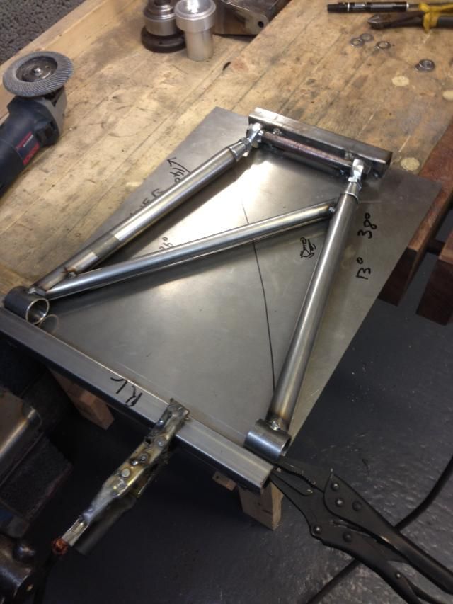
Bit of an update, got my rear hubs fully welded, and made my front wishbones, just waiting on my mushrooms for the front so I can fit my hubs

Oh and got my rack and got it fitted, need some steering extensions now

Also I'm after a column if anyone's got one?


Onto the rears next, hopefully get some wheels on it before christmas

twinturbo 7th December 2014 07:26 PM

Try ebay for a column, or your local scrap yards.

That's a very clean garage!

TT

Rosco 7th December 2014 08:12 PM

Quote:

Originally Posted by twinturbo (Post 99435)
Try ebay for a column, or your local scrap yards.

That's a very clean garage!

TT

Yeah I've got my eye out but I'm not paying £150

Haha thanks, that's my garage, I do all my fabricating in my workshop at the bottom of my garden!

Rosco 15th December 2014 07:58 AM

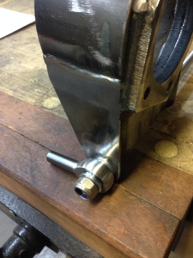
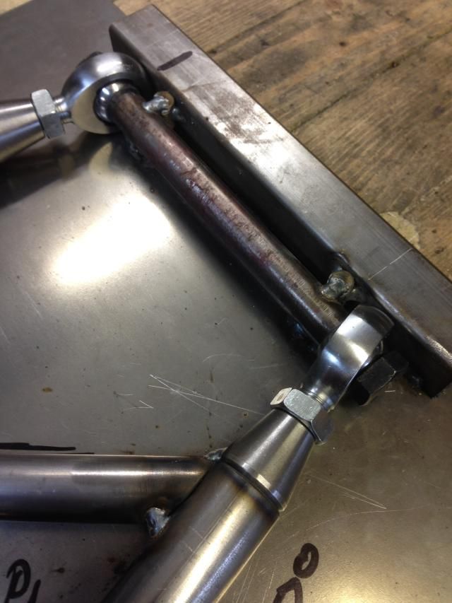
Well had a full day on the car today, got my front hubs fitted then cracked on with my rear wishbones,


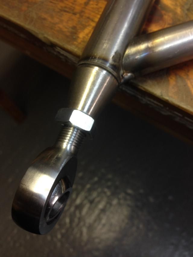
I had offered up some rod ends on my rear hubs, and checked with a 13" wheel template from team dynamics, and they will fit


Rosco 15th December 2014 08:00 AM


I don't no why but I have the latest book with the new 10mm longer wishbones but the jig drawings look like they haven't been changed, so I had made my jigs to that, then when I had made a wishbone and checked the bush centres they were 10mm short, to say I was unhappy was an understatement, I can't believe there's nothing on the amendments page just to give you a heads up, I think i will get away with it as I have wound my rod ends out 5mm and I might skim 5mm off the matting face on the stub axle or put a spacer behind the hub, so a std driveshaft fits

The rod ends are still in the tube insert a full 1" and they are only threaded that much so that's ok, just didn't really want them wound out to far


Rosco 15th December 2014 08:00 AM


Just got to sort some spaces and washers out for either side of the rod ends

flyerncle 15th December 2014 10:53 AM

Quality !;)

K4KEV 15th December 2014 01:01 PM

Very tidy indeed, keep it up mate

garyt 15th December 2014 07:05 PM

nice work and good progress, keep the pics coming :)

Rosco 15th December 2014 08:24 PM

Cheers guys

I like to get a bit done most nights, i got a spot of paint on a few of my sierra bits, only a thin coat so probably give them another coat


Rosco 20th December 2014 07:58 PM

Got my rear wishbones back from the welders and built up my rear hubs and got it all together also put my front hubs back on


Rosco 20th December 2014 07:59 PM

Fitted the old calliper to double check clearance, it's just the handbrake bit that needs modifying but I had read about this already


Rosco 20th December 2014 07:59 PM


Rosco 22nd December 2014 07:35 AM

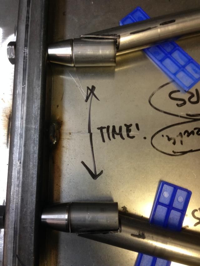
after sleeping on this a couple of nights, im going to remake the rear wishbones so the rod ends are straight, and have a bend in the side tubes, its not because of the angle its more to do with the clearance either side of the hub, as when you wind the joints in and out the gap changes, also they could do with being 5mm longer to suit std drive shafts, as the jig drawing in the book was wrong

Rosco 26th December 2014 08:28 PM

Well got a bit of time on my mk2 rear wishbones today, decided against the bend so notched them on the angle instead
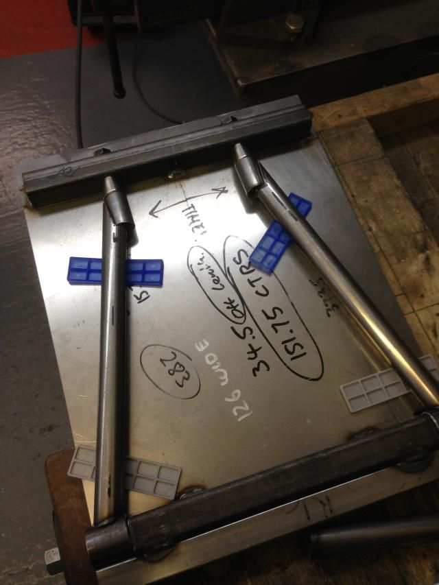


I'm thinking about putting a tube here, notched round the two
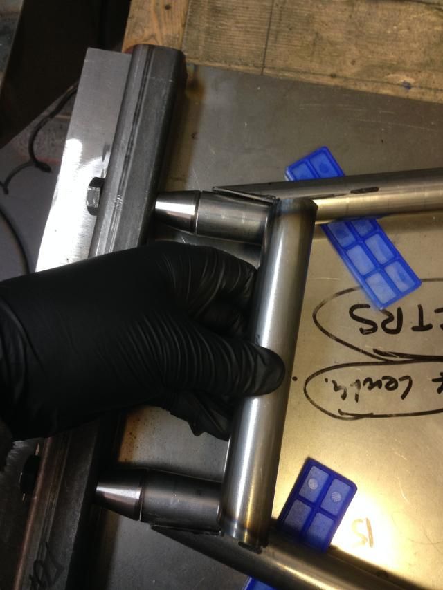


And a tube at the back, obviously longer
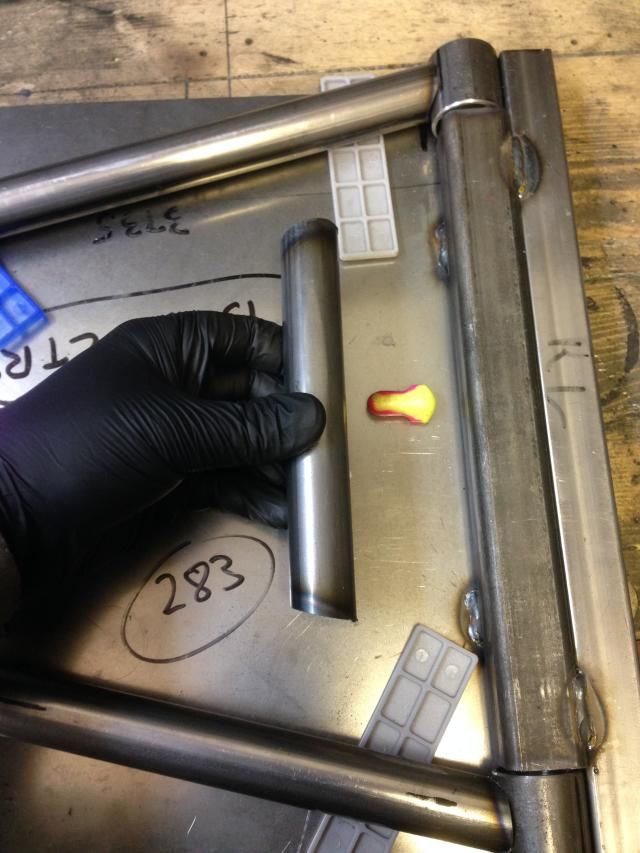


These tubes are 25mm diameter, does anyone think I need a diagonal, I could use 19mm tube, just trying to keep the weight down, I have seen rear wishbones with no diagonals just two cross bars like in my pictures

Rosco 27th December 2014 03:28 PM

Got a bit more done this morning


Rosco 28th December 2014 08:23 PM

Well had a good day, went and collected an engine from Malc at Yorkshire engines, was a long drive there and back, left at 7:30 and got home about 2:30

It's a 2010 zx10-r


And a fancy shot of my garage


Dualist 30th December 2014 05:49 PM

Those new arms look really good mate. Like the engine too.

Rosco 30th December 2014 09:56 PM

Cheers for the comments!

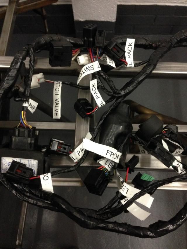
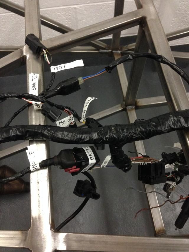
Sat down with my bike loom and labeled every plug using the wiring diagram to work out what's what

I think I'm going to use the bike loom as a base and extend and alter it to suit
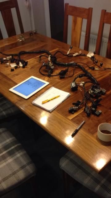


Oh how I love my label machine!

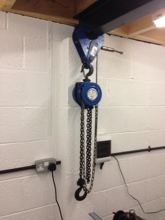
Also my mate gave me a hoist, it was filthy so gave it a good clean and re grease, also shortend the loop chain from about 4 meters to a small hoop

ayjay 31st December 2014 12:57 PM

Whens the divorce ?:o

Rosco 31st December 2014 06:02 PM

Quote:

Originally Posted by ayjay (Post 99523)
Whens the divorce ?:o

Haha, not yet, she's putting up with it at the min :D

Rosco 31st December 2014 06:02 PM

Bit more done today, had my dad helping me today!

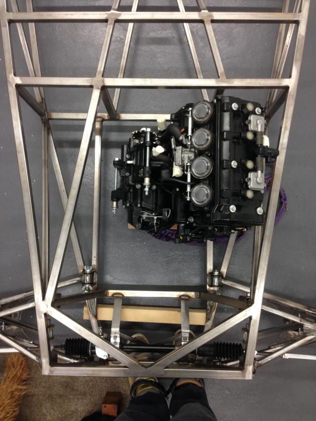
Got the engine slung up so it's picking it up somewhere near level of how it will sit in the car


Then decided to make a trolly for the rsj as the clamp I had didn't slide very wheel


Rosco 31st December 2014 06:03 PM


Then we made a trolly to sit the engine on, so we could drop the car over and move it around, then once happy with the position I get get the mounting cradle sorted without having to have it dangling in mid air


Rosco 31st December 2014 06:03 PM

I can rase the car up or down to alter the mounting height, I'm just waiting to hear back from AB performance on his zx10 sump height, I'm hoping to have the underside of the sump flush with the underside of the car

I need to decide on position next, from the pictures I've seen most seem to be mounted towards the rear of the engine bay

But some seem to be straight and some to be on an angle parallel with the side rail, on reading it looks like the output flange and the diff flange are supposed to be parallel, if anyone could help out that would be great
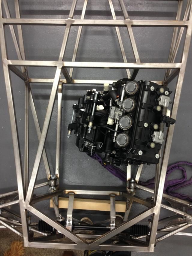


Thanks for looking

wylliezx9r 31st December 2014 07:10 PM

When I had a bike engine in mine it was parallel with the Centre line of the car like your 2nd picture and everything worked as it should. If I remember correctly when the car was corner weighted it was 520 kg with a full tank so there's a benchmark for you.

I'm running S2000 power now though and I much prefer the nature of a car engine but horses for courses and all that :D

Tatey 1st January 2015 08:50 AM

Ross you want the input and output flange to be as close to parallel as you can to prevent any vibration. When setting the height/offset of the engine you just need to make sure you don't go above 7 deg on each universal joint otherwise you run the risk of shortening the lifespan of the bearings. The smaller the angle the better though.

It's not the be all and end all if they aren't parallel/coaxial and you end up running different angles on both UJ's, it will just introduce more vibration into the system which essentially being a race car you won't really notice. If you were designing a tin top designed to cruise along the motorway at high speed you really don't want to feel that vibration.

If you have a look at the shaft drive Triumphs you will see that only has 1 UJ meaning there isn't a second UJ to cancel out the speed variation and therefore the vibration in the system. And the rear wheel pivots the angle of the joint changes meaning the vibration in the system increases. So don't get too hung up on trying to get it spot on.

Rosco 1st January 2015 01:20 PM

Quote:

Originally Posted by wylliezx9r (Post 99537)
When I had a bike engine in mine it was parallel with the Centre line of the car like your 2nd picture and everything worked as it should. If I remember correctly when the car was corner weighted it was 520 kg with a full tank so there's a benchmark for you.

I'm running S2000 power now though and I much prefer the nature of a car engine but horses for courses and all that :D

Ok cheers, s2000 would have been my choice if I was going to go car engine :D

Rosco 1st January 2015 01:24 PM

Quote:

Originally Posted by Tatey (Post 99542)
Ross you want the input and output flange to be as close to parallel as you can to prevent any vibration. When setting the height/offset of the engine you just need to make sure you don't go above 7 deg on each universal joint otherwise you run the risk of shortening the lifespan of the bearings. The smaller the angle the better though.

It's not the be all and end all if they aren't parallel/coaxial and you end up running different angles on both UJ's, it will just introduce more vibration into the system which essentially being a race car you won't really notice. If you were designing a tin top designed to cruise along the motorway at high speed you really don't want to feel that vibration.

If you have a look at the shaft drive Triumphs you will see that only has 1 UJ meaning there isn't a second UJ to cancel out the speed variation and therefore the vibration in the system. And the rear wheel pivots the angle of the joint changes meaning the vibration in the system increases. So don't get too hung up on trying to get it spot on.

Ok mate thanks for that, it's just all the mk's I've seen are mounted on the piss with no effort to keep the flanges parallel

Rosco 1st January 2015 01:24 PM

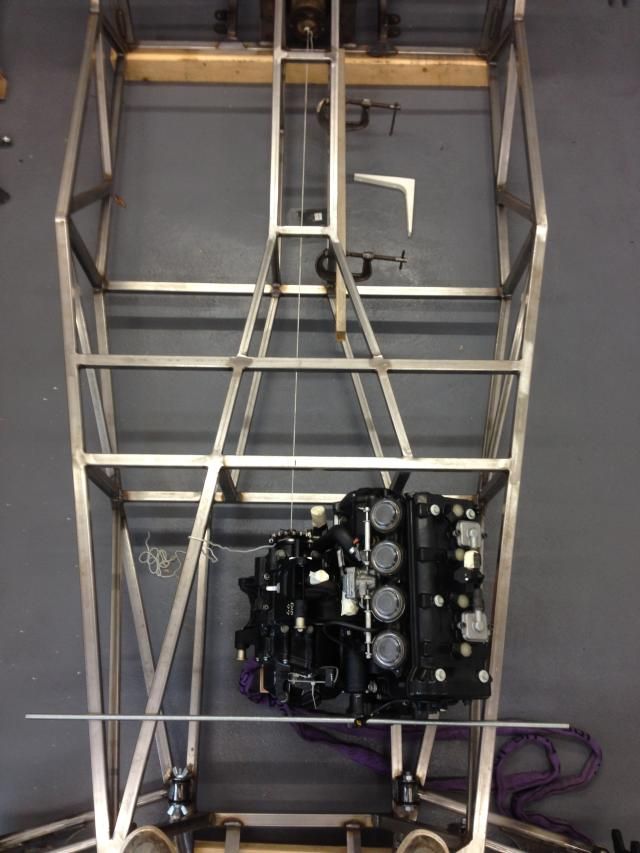
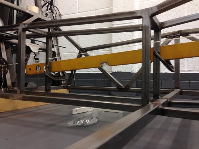
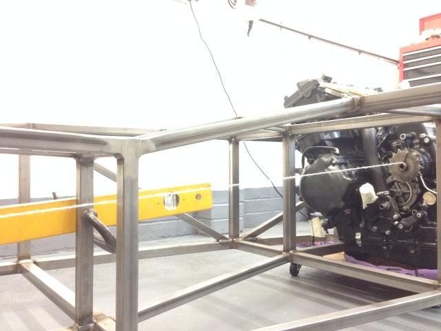
Just been looking at engine position and I'm sort of happy with this current position

Running the engine dead inline it seems to put the output shaft in a good position

If I turn the engine so it's parallel to the outer chassis rail it just skews the output shaft but doesn't improve the position for the prop
And from what I've read it's better for the flanges to be parallel
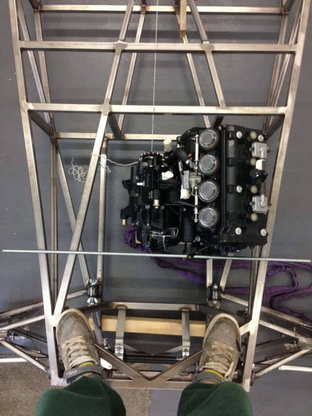


In this position the total prop length would be 1460mm but I could move the engine back 50mm if I moved the passenger footwell upright back

I have strung a ling between and it's at an angle from the horizontal of about 4 deg, I take it I will still need a 2 piece prop with a centre bearing and a slight kink in the centre so the UJ's aren't running straight

Rosco 1st January 2015 01:25 PM


My main doubt is the more photos of people builds I look at the more seem to have the engine skewed

If anyone could agree or disagree that would be great!

flyerncle 1st January 2015 02:20 PM

Argument was about angle of u/j's in the prop but you would need a center bearing anyway.

Tatey 1st January 2015 02:23 PM

Ross you can just use a 2 UJ prop setup with the UJ's 90 degrees out of phase, no need for a centre bearing. You only tend to use a centre bearing when you have 3 UJ's in the proshaft as you need the centre bearing to support the centre UJ otherwise it would be free move in free space.

Rosco 1st January 2015 02:41 PM

Quote:

Originally Posted by flyerncle (Post 99548)
Argument was about angle of u/j's in the prop but you would need a center bearing anyway.

Sorry I'm confused, what argument?

Rosco 1st January 2015 02:43 PM

Quote:

Originally Posted by Tatey (Post 99549)
Ross you can just use a 2 UJ prop setup with the UJ's 90 degrees out of phase, no need for a centre bearing. You only tend to use a centre bearing when you have 3 UJ's in the proshaft as you need the centre bearing to support the centre UJ otherwise it would be free move in free space.

Yeah I thought that but I thought it was a bit long for a single prop?

Rosco 1st January 2015 03:02 PM

Few exhaust clearance pics


That's looking straight at the side


That's looking straight down the axis of the exhaust ports


And that's a ruler coming straight out of the port


Hopefully I might be able to drop the engine down a tad more, just waiting on AB performance to give me some sump dimensions

Rosco 5th January 2015 09:09 PM

Well spoke to AB performance today, real nice chap with some good ideas backed up with some good evidence,

So I've moved it again, haha


Rosco 5th January 2015 09:09 PM

Think I've got clearance around everything that I need to have

So Tatley off the haynes forum who lives not to far from me has kindly lent me his body work so I can mock things up
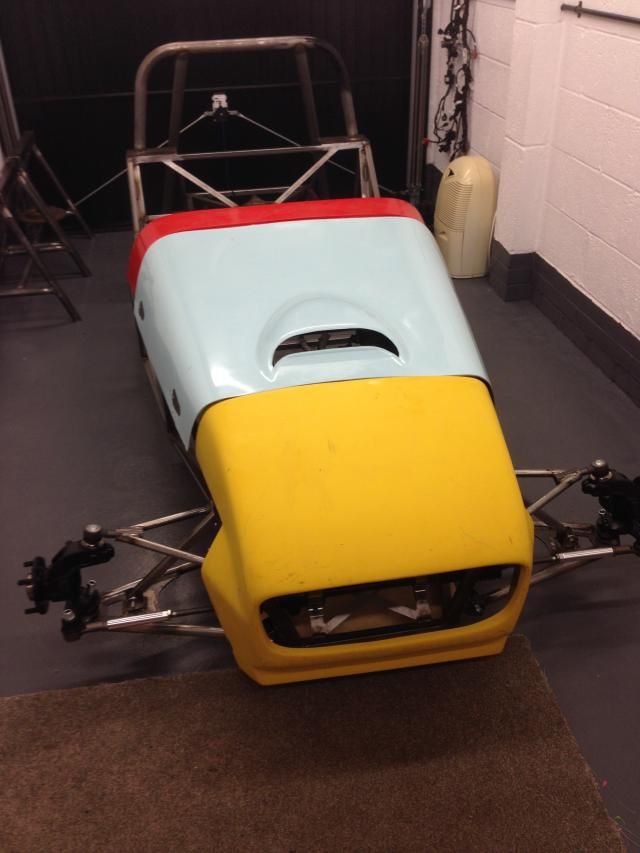


Looking a bit like a car!
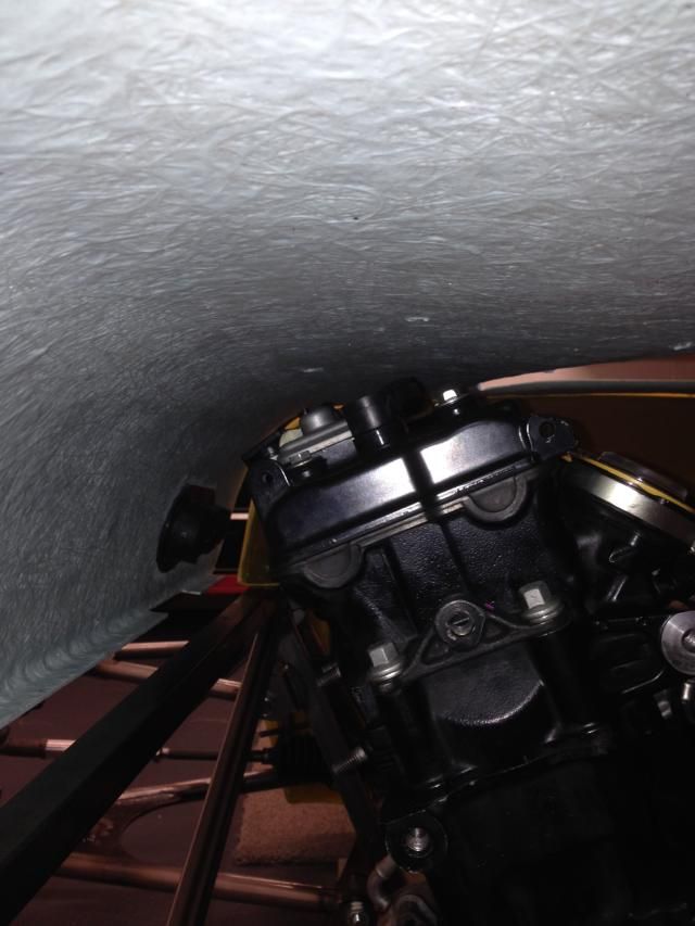


There's a bit of clearance over the top, this is saturn body work but I'm holding that the exquinox may be has a bit more

jps 6th January 2015 08:29 AM

Quote:

Originally Posted by Rosco (Post 99581)
There's a bit of clearance over the top, this is saturn body work but I'm holding that the exquinox may be has a bit more

I believe the Equinox scuttle and nosecone come up taller - i can measure mine this evening and post some pics if it helps? Actually, now that i've got my engine mounts done, it's about time that I do what you have anyway!

Rosco 6th January 2015 10:43 AM

Quote:

Originally Posted by jps (Post 99582)
I believe the Equinox scuttle and nosecone come up taller - i can measure mine this evening and post some pics if it helps? Actually, now that i've got my engine mounts done, it's about time that I do what you have anyway!

yes if you wouldn't mind, that would be great


All times are GMT +1. The time now is 06:13 PM.

Powered by vBulletin® Version 3.6.4
Copyright ©2000 - 2024, Jelsoft Enterprises Ltd.