Upright Dimensions
I'm in the planning phase of my kit car fantasy. It'll probably be some time before this is turned in to a reality but you've gotta dream right?!
I was thinking of using an mx5 as a donor, including the front uprights. To plan the suspension I need the dimensions so that I can get the angles correct. Does anyone have the distance between the top and bottom mounts on the uprights as well as the location of the steering arm ball joint on the upright? Failing that I'll have to use my E46 as a donor (which could be interesting) seeing as I can't sell it (nudge nudge)... Thanks for any information. |
Saturn have all the parts to hand as he has just built one using an MX5 donor.
|
Hold on for just a bit, Saturn is about to release a set of drawings for an MX5 based Roadster. Look in this thread.
http://www.haynes.co.uk/forums/showthread.php?t=5753 Quote:
|
http://locostcadfiles.wikispaces.com/Spindles+and+Hubs
If you don't have Solidworks I'm sure if you give Jason an email he'll export it to a file that your software can support. There's more to suspension design than making it "fit" the Haynes chassis. My dealings with the Haynes's supension shows that as the car rolls it goes into positive camber, not ideal. Spend a bit of time to get it right, you'll be far more satisfied with the results. ATB Will |
Quote:
Perhaps you would care to enlighten us with your dealings of the Roadster suspension !!?? :confused: Rather a strange first post to make on the forum ( Sorry if that comes over as a tad hostile, it's not meant in that way ) Perhaps an intoduction to yourself would have made better subject matter for your first forum post ;) :) |
Quote:
However my first post was actually to supply the OP with the information he asked for, as no-one else seems to have answered his question, but when you've quoted me you seem to have deleted the important part of my reply and just concentrated on the obsevation I've made about the design. which I have said isn't ideal, nothing else. Here is what my observations are, please study the drawing below 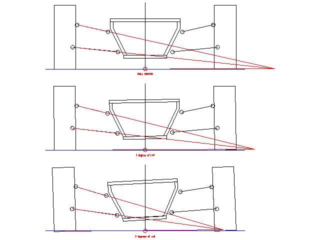 I have simplified the drawing to show what is important, the pivot points on the chassis and the hubs are represented by the circles. The drawing represents a car to book dimensions on 195/50/15 tyres with a ride height of 4" (as seems to be most popular for it) in static, 1 degree & 3 degrees of body roll. And no, I haven't doctured any drawings to exagerate this. As you can see the outside wheel (the one loaded in cornering) gradually lifts the inside edge of the tyre clear of the ground, pictures on the Saturn website back this up, the reason the car may feel "balanced" is because both ends do the same. What I am saying is that the design can be improved, if you are building using the MX5 upright then with a little time and patience you can achieve a design that will provide good wheel control in roll, it's always a balancing act but it is possible to get very close to ideal. |
Perhaps you can show us what happens with a real tire that distorts under load, instead of your depiction of a solid inflexible tire?
I have never seen a rectangular tire in the real world, which is where we drive our cars. Quote:
|
Bet me too it. How ever if your that worried about front end goings on mid corner you should be looking into this sort of set up.
http://www.daxcars.co.uk/start.htm |
Predicting what a tyre does in deflection is a bit of a grey area, as the amount of distortion varies from one make to another, the reason a lot of the more performance orientated vehicles use tyres designed specifically for them, it's not so prices can be fixed but because the chassis designer would have worked closely with that perticular tyres characteristics to fine tune the suspension.
|
Quote:
|
| All times are GMT +1. The time now is 08:37 PM. |
Powered by vBulletin® Version 3.6.4
Copyright ©2000 - 2025, Jelsoft Enterprises Ltd.