CP3/4 driving me mad!
This is probably very obvious, but ive read it loads now and im just getting more confused!
Right the 4 holes with nuts welded, go to the outside. the shock bracket to the inside? right? The shock bracket is off-centre towards or away from the chassis rail? The 4 holes are are off-centre towards or away fom the chassis rail? I know they are a mirror image of each other but thats not helping, im well mixed up :o Cheers Will |
1 Attachment(s)
The nuts are welded on the underside along with the shock bracket as the plate with the rollbar welded to it will sit on the top. For the other questions not sure if this will help and I'm doing this from memory so I'm probly wrong! Note this would be viewing them from the back of the car.
|
This is how they should look,
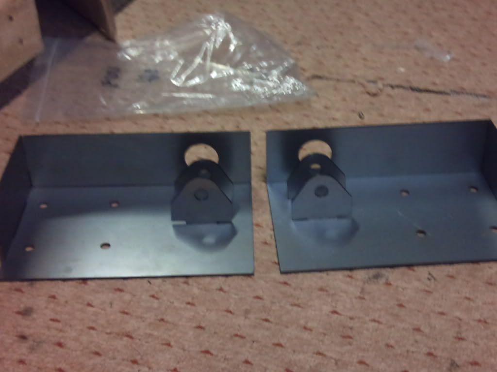 Hope that makes things clearer ;) TK |
Cheers guys,
my plates are like that John, thanks for the photo. The only thing im not sure is wheter the holes should be biased towards or away from the chassis. it looks like away in your photo? but that could be an illusion! Time i went to bed, my head is battered with these plates |
Don,t forget that when looking at the great photo John has supplied that as you look at them in the pic....that the front edge (in the pic closest to the camera) sits on top of SB2 & that part RS15 needs to be welded along the short edge ( beside the shock bracket in the photo ).
This then all becomes clear ( I hope ) when you turn the assembly the right way up & sit it on top of SB2 . Hope that helps a little :) cheers andy |
Cheers Andy, when i flip them they go like you say. the shock bracket faces out, then RS15 is about 25mm back to allow it to mate with SB2.
But the bolt holes are not central on the plate, this is what i might have messed up. Across the plate you come in 35mm have a hole, then another 70mm have a hole. then it should be 45mm to the other edge of the plate. 150mm in total. I take it the 45mm gap is towards SB2? when plate is right way up to be mounted Sorry, I dont know ive made this so complicated!! :confused: |
If you look at the drawings(bottom drawings) on page 173....look at the sketch dimension drawing in the left upper ignoring the CAD photos...
this sketch shows the assembly for the NEARSIDE, it is basically like an Xray vision picture, you are looking down thru the top plate. You are correct in saying the bolt holes are NOT central to the plate, as in the diagram....the forward holes are 45mm from the front leading edge ( that sits on top of SB2) & 20mm (this being the outer hole) in from the shorter edge of the top plate then 70mm in & likewise for the other 2 holes creating a 70mm box with all 4 holes. So you are correct on the 45mm...70mm....35mm spacings & yes the 45mm gap is the one that sits over the SB2 rail. I will say that the most important point of this assembly is getting the shock bracket in the correct position as this then lines up with the shock mounting point in the rear upright. The 4 bolt holes are just for attaching the mounting plate for the roll bar . 1 more point to note........when you weld RS15 into position don,t forget to leave a 3mm gap along the back edge which is where CP6 is then welded into position ( this is the tiny dotted lines in the sketch that are not easy to see/notice at first glance ). The 2 CAD photos at the bottom of page 173 are wrong as they imply that the shock bracket is positioned on the outside when turned over ......the shock brackets should be located towards the diff cage .......close to where D12 if that makes sense & the 4 bolt holes are positined towards the outer close to SB1,s if that makes sense :) . Sorry for long winded reply :o not easy to explain , hope it helps . cheers andy |
Quote:
In this photo, the assembly on the LEFT of the photo is the PASSENGER side assembly & the other is the DRIVERS side assembly. cheers andy |
That has cleared it up beautifully :D
Andy your a legend! |
Quote:
Glad the info helped . cheers andy |
| All times are GMT +1. The time now is 11:02 PM. |
Powered by vBulletin® Version 3.6.4
Copyright ©2000 - 2024, Jelsoft Enterprises Ltd.