
|
|
#11
 13th October 2012, 09:42 PM
|
|||
|
|||
|
Hi shorty.
If you want to see a built up chassis at all drop me a line as I'm only in gosforth and the kettle is always on! David
__________________
Click to see my build photos on Flikr http://www.flickr.com/photos/67112582@N03/ Saturn MX5 Based Chassis, Limited Slip Diff & 2.4 Quick Rack. Build cost.... seems to be spending more on tools than car bits at the moment! (they will be handy in the future though). Car iva'd and passed 15/08/2014. Finished weight 572kg. 
|
|
#13
14th October 2012, 10:10 AM
|
|||
|
|||
|
Actually sb3 must be in the correct position as the two sb4 were a good fit although I didn't weld them in as my diff is 7.5" and so will mount them later as recommended by Andy to save cutting the diff lugs.
Andy you did say the sb5/6 mitre angle can confuse but I'm sure I had it right, mitre angle to top and 52 deg to sb3. May have just been a tight fit and need a quick clean off rough edges. I will probably have the same bother with all diagonal tubes ensuring they are in exact position.
|
|
#14
14th October 2012, 03:15 PM
|
|||
|
|||
|
Turns out I was just being stupid, marking dimensions on the back rather than front as it clearly shows on page 38, so its the shorter corner of the mitre cut that is lined up.
Next question... The book says noting the position of the diagonal braces in relation to the other rails. but I'm not sure about D1 and D2 where they fit to U1 and U2 as having them flush with outer frame doesn't look like it has much contact. I have a picture so you guys can check it but will have to do that later as not at computer. Last edited by Shorty : 16th October 2012 at 08:33 PM. Reason: Edited as the book does not say line up with outside
|
|
#15
14th October 2012, 07:04 PM
|
|||
|
|||
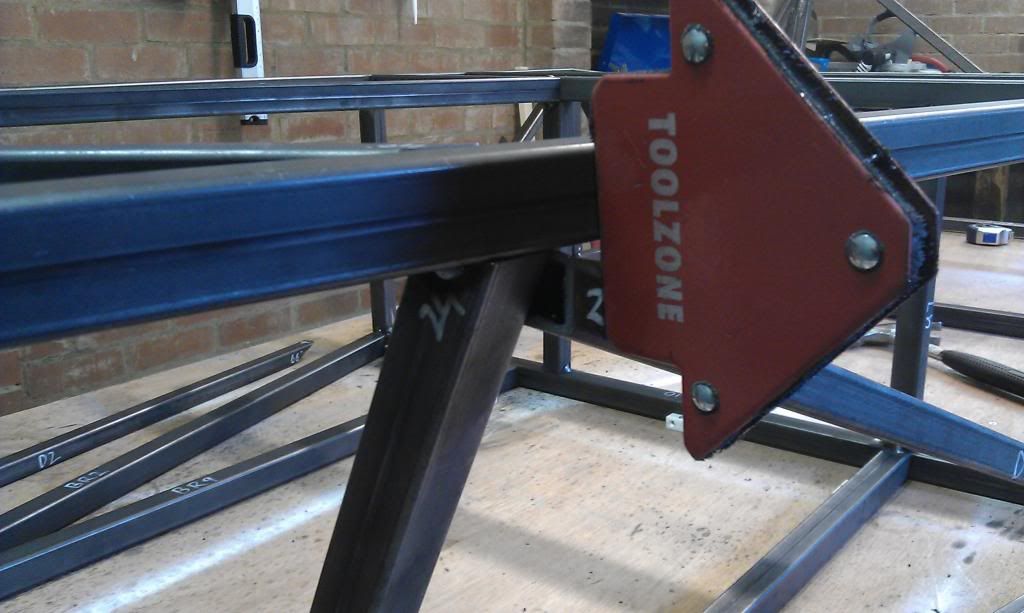 Well if the picture has worked you will see TR1 across the top, thats U1 coming up to TR1 with the outer front corner lined up with the outside of TR1. Now if I do have U1 correct, the magnet is holding D1 flush with the outside face of TR1 and does not look right. I would expect that to be flat up against U1 further in to give more support. I had a quick look through book but D1 doesn't seem to have even been fitted further on. I understand people leave this out until engine fitted but I just want to get everything clear and I can remove later if needed.
|
 |
| Thread Tools | |
| Display Modes | |
|
|


 Linear Mode

