
|
|
#11
 11th August 2011, 01:58 PM
|
||||
|
||||
|
Thanks Dave, that makes sense to just remove the fan switch and use it as an inlet for the expansion tank. Another random question, I've got what looks to be either a coolant hose or a vacum hose that goes from the inlet manifold right infront of the thermostat (near cylinder 1) that then goes around the front of the engine and connects in on the head on the exhaust side above the spark plug for cylinder 1. Any idea if this a vacum or coolant pipe and if it is a coolant pipe how should i re-route this as I won't have any coolant outlets on my bike carb manifold?

|
|
#12
11th August 2011, 03:44 PM
|
||||
|
||||
|
That is a pipe that flows water back into the head to help the engine warm up quicker. I didn't bother with it on mine.
I unscrewed the pipe fitting above the exhaust port. Cut off the spigot and welded up the hole. Screwed it back it. Job done. You can just make it out in the below picture. 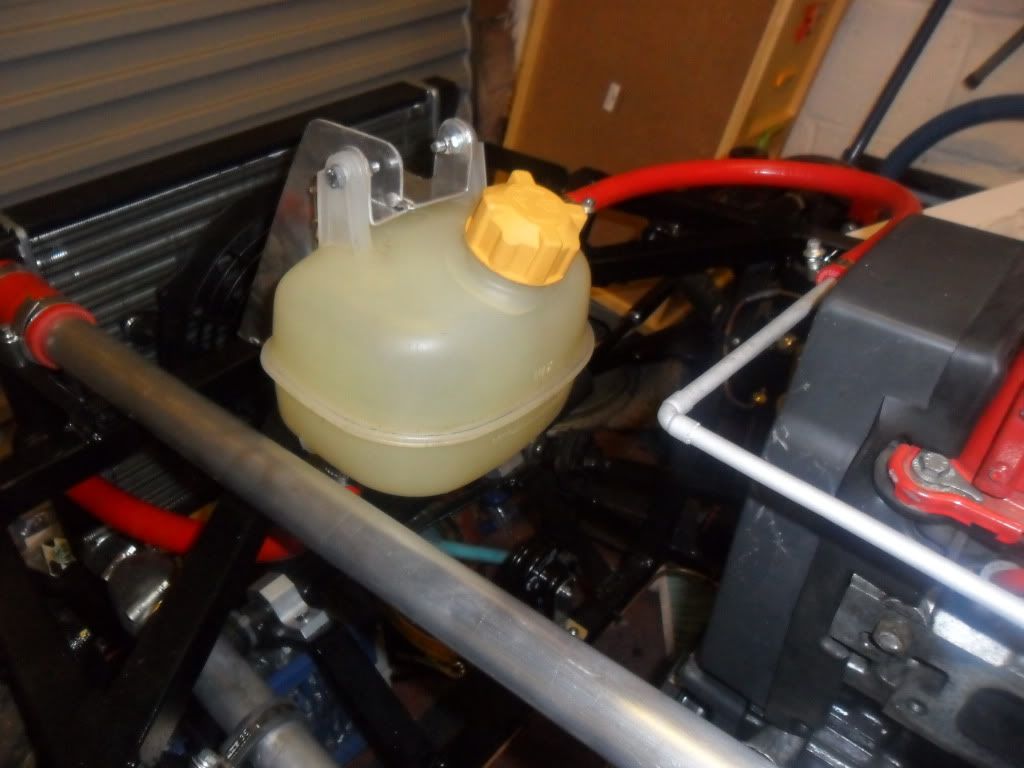
__________________
http://s831.photobucket.com/user/dav...ter%20Pictures OTR 01/05/14 - 1.6 CVH, Type 9, Bike Carbs, Megajolt
|
|
#13
11th August 2011, 04:17 PM
|
||||
|
||||
|
Gotcha, thought it might be a coolant hose
 So if I've got it right now, here's how it worked in the sierra vs how I should set mine up bearing in mind i'll use the 1.6 cvh thermostat and bike carbs? Hopefully these pics might help someone else one day! So if I've got it right now, here's how it worked in the sierra vs how I should set mine up bearing in mind i'll use the 1.6 cvh thermostat and bike carbs? Hopefully these pics might help someone else one day!
|
|
#14
11th August 2011, 04:48 PM
|
||||
|
||||
|
Your modified diagram is exactly how my cooling system is done, and I know works well from when I have had my engine running.
__________________
http://s831.photobucket.com/user/dav...ter%20Pictures OTR 01/05/14 - 1.6 CVH, Type 9, Bike Carbs, Megajolt
|
 |
| Thread Tools | |
| Display Modes | |
|
|


 Linear Mode

