
|
|
#21
 29th March 2012, 10:34 AM
|
|||
|
|||
|
Quote:
Rather than guess at the problem or assume someone else has solved the problem on their design. (westfield still have problems with their solidly mounted arangement.) lets try to understand the problem and then solve it! Firstly the failure mode needs to be understood. Currently no one other than Jenks seems to have correctly identified what actually happened to cause the failure and so we make no progress in resolving the problem we just create a pile of broken diff carriers! To understand what has happened we first need to understand how the power plant assembly in the donor vehicle works. The engine and gearbox are rigidly bolted together and the powerplant frame is tightly fitted to the gearbox and the diff. This creates a complete unit which is mounted to the front subframe by two mounts on the engine which primarily are to control the engines verticle movement over bumps and reduce vibration transmitted to the passenger cabin and two rubber isolators on the diff carrier which are to isolate vibration. They provide some small resistance to rocking side to side motion but cars with a power plant assembly such as the MX5 have very little side to side movement under even the hardest accels due to the powerplant all being connected together and the torque forces largely canceling each other out. The torque reaction to the driven wheels is resisted as the diff cannot lift the engine/gearbox assembly attached at the other end of the powerplant frame and thus the diff is constrained totally in movement in this direction. In mounting the diff in isolation the nose of the diff needs to be tightly constrained and herein lays the cause of the failure. The ex engine mount is being used in tension for which it was not designed and can therefore not sufficiently prevent the diff nose from moving vertically upward under drive as the diff reacts to the torque appplied at the rear wheels. The two mounts on the diff carrier were never designed to work in this way and the diecast ally case fails exactly as described. This problem has a well trodden path and the solution lays in controling the diff nose. Triumph had the same problem in the 1950's when designing the triumph herald/spitfire and they resolved it by bolting a bracket to the diff nose and stiff mounts to the chassis and I would suggest a similar arangement with some sort of laser cut bracket that can fix to the mazda PPF mounting and via suitable mounts to the chassis. Hope this has helped people to understand the problem and enable all to work toward a solution. BV  Last edited by Big Vern : 29th March 2012 at 10:45 AM. 
|
|
#22
29th March 2012, 11:21 AM
|
|||
|
|||
|
Quote:
It's obvious where the rear cradle is weak as it is open rectangles with no triangulation and the diff is fixed to this........less is more usually and take a good look at how Marc Norden has done the MNR, simple yet very effective.
|
|
#23
29th March 2012, 01:20 PM
|
|||
|
|||
|
Quote:
It is how the diff is mounted to the chassis not chassis flex itself that has caused the problem. The diff has moved because its not fixed to the chassis in a way that constrains the movement of the diff nose. Quite simply the diff nose mounting rubber has too much movement in it. The nose of the diff rises as a reaction to the road wheels driving forward, the twist on the alluminium diff carrier exceeds the strength of the carrier and it fails exactly as in the pictures NTS posted. What is needed is a better diff nose mounting arangement to constrain the movement. As said previously, Mazda designed the diff mounts for vibration isolation rather than to constrain torque reaction. I like the way MNR have mounted the two rear mounts but they do still have diff problems - just view the locost usa site and have a look. BV
|
|
#24
29th March 2012, 01:41 PM
|
||||
|
||||
|
I would tend to agree with BV ....I have seen the diff cage in question and there is NO evidence of any weakness/distorsion whatsoever ...if fact there was barely a scratch which is testament to a good design rather than poor
|
|
#25
29th March 2012, 02:05 PM
|
||||
|
||||
|
I've used two volvo engine mounts top and bottom orientated so that the top one is resisting vetical movement and the bottom one horitantal movement. So I'm covering any rotational movement. It looks nasty in this image as I haven't finished bracing the chassis brackets and tidying them up.
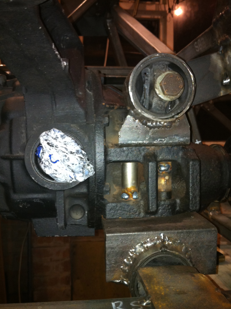 Not a great picture. I'll try and get a better one in good lighting. Last edited by CTWV50 : 29th March 2012 at 02:07 PM.
|
|
#26
29th March 2012, 03:08 PM
|
|||
|
|||
|
Quote:
|
|
#27
29th March 2012, 04:38 PM
|
|||
|
|||
|
Quote:
I have seen no evidence to suggest the chassis doesn't take the forces placed upon it which arn't great in the donor vehicle anyway. The two mounts for the diff carrier are just as they are in the vehicle I looked again at the ones in my MX5 at lunchtime. Whilst I suspect the NTS/Saturn front bracket would crack adjacent to the weld that was not the point of failure in this case. It was the rubber ex-engine mount not being the correct type to restrain the diff nose verticle movement that has caused the failure and judging by some posts on locost usa some MNR builders are having similar problems. Two or three bloggers I looked at last night are experimenting with different stiffnesses of mount to try and overcome diff carrier cracking so I'm by no means convinced MNR have it right either, and I know the westfield miata has had problems. CTWV50 has the right idea but I seriously doubt engine mounting rubbers will be sufficiently stiff to control the diff voided bushes will still have too much movement. Something along the lines of a poly bush at around shore 90 acting as CTWV50 has his will control the diff leaving the two isolators in the diff carrier largely to do what they do in the donor car which is to soak up vibration. Indeed it may make more sense to ingore the two mounts on the diff carrier altogether and go for robust mounting of the diff via the PPF mounting system. Has anyone considered using the back part of the PPF and mounting that to the chassis I wonder. BV Last edited by Big Vern : 29th March 2012 at 05:02 PM.
|
|
#28
29th March 2012, 05:15 PM
|
||||
|
||||
|
Hmm, thanks for the costructive critisism, I'm only running a cheap 1.6 open diff atm so if it does fail with this design I'll upgrade to a torsen and rethink the design. I think most people will of thought about a solid mounting to the chassis but surely you would end up with alot of vibration through the chassis which would cause other reliability issues.
edit: Have you got any links BV for the failures on locostusa? What's your source for the westield miata issues? Cheers Chris Last edited by CTWV50 : 29th March 2012 at 05:27 PM.
|
|
#30
29th March 2012, 06:15 PM
|
|||
|
|||
|
Quote:
Steve
__________________
Cost So Far = £376.62  I LISTEN TO THE VOICES IN MY TOOLBOX I LISTEN TO THE VOICES IN MY TOOLBOX
|
 |
| Thread Tools | |
| Display Modes | |
|
|


 Linear Mode

