
|
|
#181
 25th October 2012, 10:55 PM
|
|||
|
|||
|
Hi Johno thanks for your reply you say you have moved upper rear shock bracket to above upright maybe I'm stupid but I don't understand what you mean maybe you could explain, also are the wishbone brackets as per book?.
Is there anywhere I could get the wishbones as your using made for me? Regards Mick. 
|
|
#182
26th October 2012, 08:11 PM
|
||||
|
||||
|
Quote:
All the suspension brackets on my car are as the Saturn build guide Rev 3 (I believe I still have this somewhere in pdf format). The rear shock mount I have moved to above the upright similar to the Sierra version. This way the shock is in line with the upright and the same length as the book. It also takes some strain off the threaded adjuster. 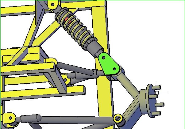 The rear top wishbone is adjustable via the bolt running through the bush with a lock nut one end and a half nut the other. This way I can alter track width on the lower wishbone and adjust camber on the top in situ. The front lower is non adjustable as all the adjustment will be on the top wishbone and steering rack. 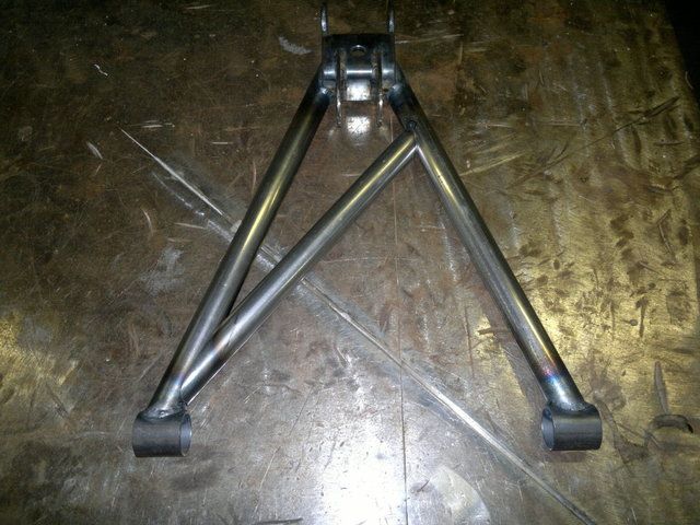 The front upper wishbone will be as this drawing and hopefully will be able to post a photo of the finished product as I have recieved my machined parts today. 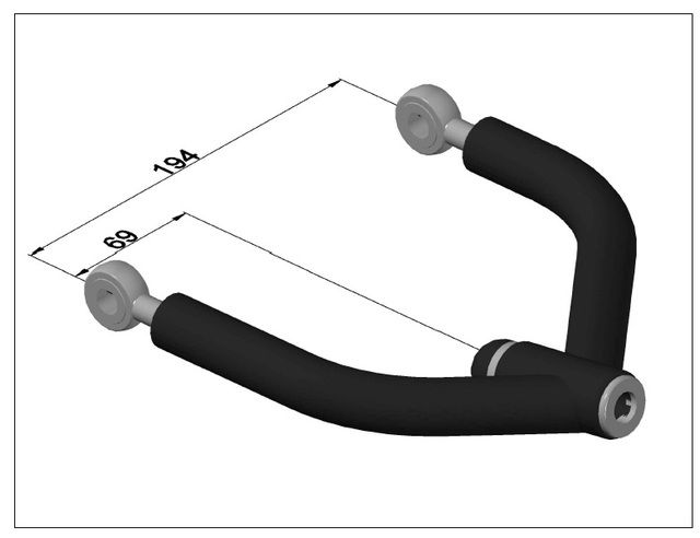 I've designed all the alterations myself and as far as I know I'm the only one with these type of wishbones. I've made wishbones for other people on here for the MX5 version only and they seem happy with them but not to my new spec. The front upper is designed to overcome the self centering problem, with adjustable inner "Rose Joints" to alter the caster as required and the only difference to the Sierra version would be the thread for the ball joint as the MX5 version uses 14x1.5mm. Just pm me if you need any further info.
__________________
Any intelligent fool can make things bigger and more complex... It takes a touch of genius - and a lot of courage to move in the opposite direction. Albert Einstein http://s1199.photobucket.com/albums/aa472/JohnoSS1/ Johno
|
|
#183
27th October 2012, 07:29 PM
|
||||
|
||||
|
Well I made my new wishbones today....
Got a bit of a panic on at one point... Started welding my tube to the bush and decided to slide my inner threaded adjuster in to see if it still fitted. Well that was a bad Idea....Slid in easy and all of a sudden it stopped moving. I even told myself before making them at no point leave inner adjuster in when welding.....dohhh. I eventually got it out with a bit of heat going over the weld with the TIG and a tap from trusty old hammer... Lesson learnt. Here's a piccy of the finished product......... 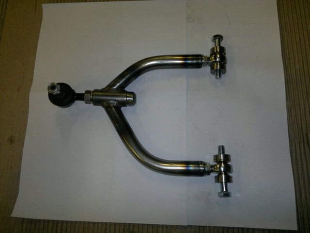 The inner adjuster is made from mild steel with a 16mm dome head welded to the flange on the adjuster which is tapped 14x1.5mm to suit the 325 BMW ball joint which has the correct taper for the MX5 upright. Adjustment for camber can be acheived in situ on the car with an Allen key and 22mm spanner without removing any parts. Caster can be altered via the "Rose Joints" which turned out to be pretty easy. Just remove the bolt and spacers and turn the rose joint in or out as required within the suspension bracket. Each end of the adjuster is a stainless machined washer to stop the locking nuts chewing up the paint/powdercoat. 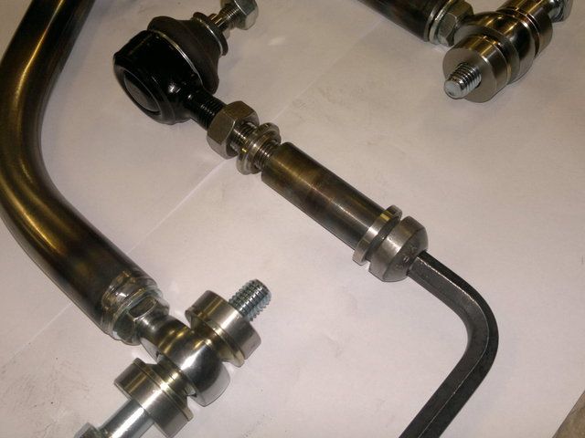 All radiuses are 2.5mm where required for IVA. The rose joints are 12x1.25 fine thread and are "Ultra High Strength" with misalignment washers both sides for optimum adjustment. I've moved the adjuster back 5mm to increase caster by about 1.4 degrees. Here's a piccy of the wishbone in place.. 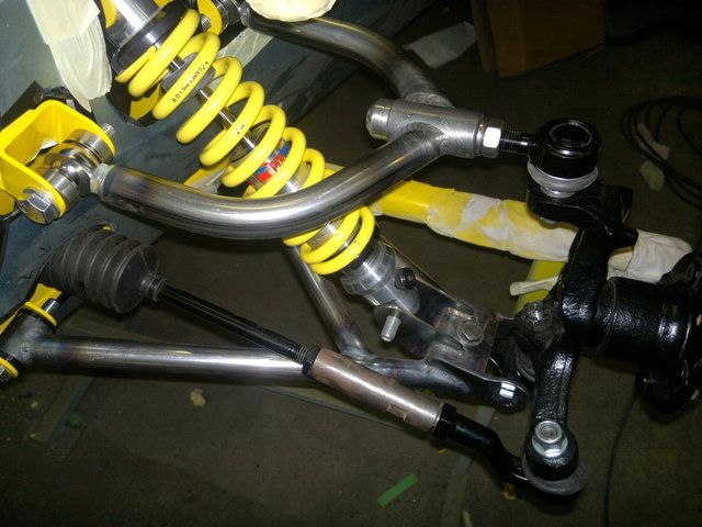
__________________
Any intelligent fool can make things bigger and more complex... It takes a touch of genius - and a lot of courage to move in the opposite direction. Albert Einstein http://s1199.photobucket.com/albums/aa472/JohnoSS1/ Johno
|
|
#184
27th October 2012, 07:35 PM
|
||||
|
||||
|
I've also been playing around with the dash.
I'm going to fix it behind the scuttle flange and cover it with leatherette (well the missus is  ). ).I'm planning on fitting the original MX5 instruments but at the moment got no Idea how to do it...LOL.....  With any luck will be able to post a photo tomorrow.
__________________
Any intelligent fool can make things bigger and more complex... It takes a touch of genius - and a lot of courage to move in the opposite direction. Albert Einstein http://s1199.photobucket.com/albums/aa472/JohnoSS1/ Johno
|
|
#186
27th October 2012, 10:13 PM
|
|||
|
|||
|
Johno,
If you look at Nathan's photos he seems to of made a good job of it and used some trim around the hole David
__________________
Click to see my build photos on Flikr http://www.flickr.com/photos/67112582@N03/ Saturn MX5 Based Chassis, Limited Slip Diff & 2.4 Quick Rack. Build cost.... seems to be spending more on tools than car bits at the moment! (they will be handy in the future though). Car iva'd and passed 15/08/2014. Finished weight 572kg.
|
|
#188
28th October 2012, 04:18 PM
|
||||
|
||||
|
Quote:
 When I fitted the top wishbone this was the first thing I checked.
__________________
Any intelligent fool can make things bigger and more complex... It takes a touch of genius - and a lot of courage to move in the opposite direction. Albert Einstein http://s1199.photobucket.com/albums/aa472/JohnoSS1/ Johno
|
|
#189
28th October 2012, 09:07 PM
|
|||
|
|||
|
Quote:
Excellent, job for the next couple weeks for me then!!!
__________________
Stew
|
|
#190
4th November 2012, 05:34 PM
|
||||
|
||||
|
Made a start on my dashboard this weekend.
I've decided to make it out of ally and it will be padded and vinyled up when done. I made a panel to hold the instrument cluster and cut a hole in the dash to to accomadate the bezel. I attached 4 thread inserts to the dash and fitted threaded rod into each. The bezel is then placed in to the dash and then the instrument cluster is tightened down onto it. 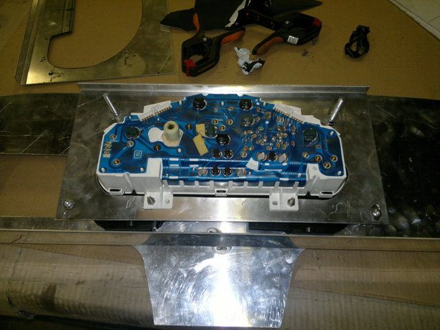 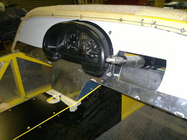 It took some sorting out but I also managed to panel underneath the dash as well, just need to fix the front edge to the dash edging angle. 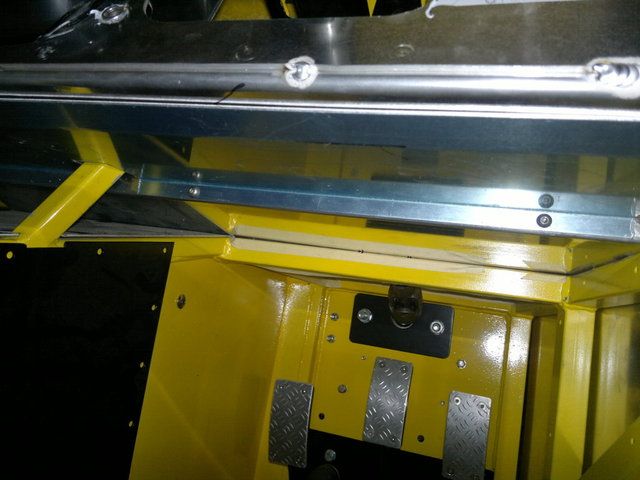 I cut an access hole for my brake pedals in the top ally panel in front of my scuttle. I will make a cover for the steering column and access hole in one piece which will be removable. 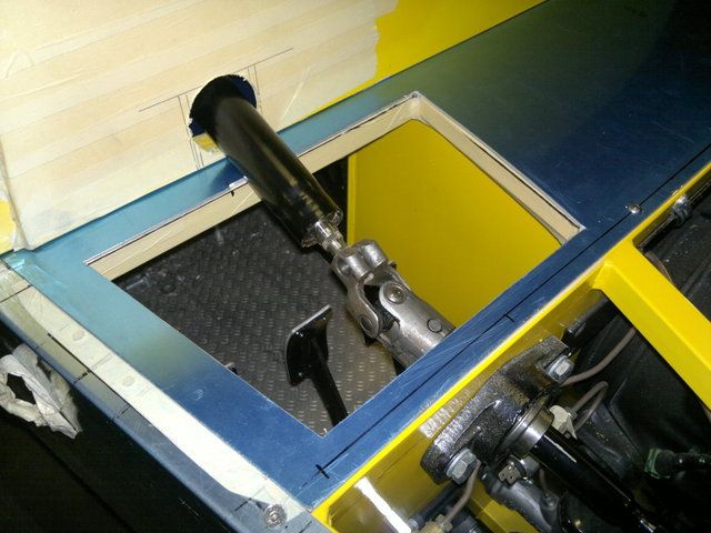
__________________
Any intelligent fool can make things bigger and more complex... It takes a touch of genius - and a lot of courage to move in the opposite direction. Albert Einstein http://s1199.photobucket.com/albums/aa472/JohnoSS1/ Johno
|
 |
| Thread Tools | |
| Display Modes | |
|
|


 Linear Mode

