
|
|
#1
 1st December 2009, 07:57 PM
|
|||
|
|||
|
Does anyone know the correct wiring arrangement for the ignition coil?
I am having difficulty find the correct wiring diagrams for 1986 sierra, this was the year when every was switched over so the diagrams change!  Anyway as far as I can tell, the ignition coil centre terminal is connected to the distributor cap I am then left with the black push on terminal (with an additional plug in component that is connected to the mounting bracket screw) and 2 Nr green wires. Logic says that the black is the negative (-), but Dogwoods diagram contradicts this! Can anyone help or have photos ???
__________________
http://www.flickr.com/photos/29404787@N03/ http://www.flickr.com/photos/41021922@N03/ http://www.flickr.com/photos/56936222@N04/ http://www.flickr.com/photos/79486076@N06/ Finished my roadster after 5 years! Number 27! 
|
|
#2
1st December 2009, 08:15 PM
|
||||
|
||||
|
Quote:
 ") Let me just check, I could have made a BooBoo...
|
|
#3
1st December 2009, 08:29 PM
|
||||
|
||||
|
Nope, just checked.
That is how I did it. I agree it looks wrong. I ain't got the car here, so cannot take a pic to show you. This diagram is only how I wired it up to get the engine running. Still happy to be proven wrong, Incase I was just lucky..  (Sketch edited to make the black coil feed come from the ign switch, and not from the batt feed, Thanks AshG) 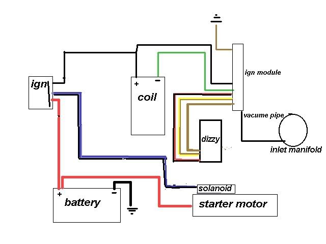 Last edited by dogwood : 2nd December 2009 at 10:48 AM.
|
|
#4
1st December 2009, 08:32 PM
|
|||
|
|||
|
Did you have a plug in component on the black (+) I really appreciate the help
__________________
http://www.flickr.com/photos/29404787@N03/ http://www.flickr.com/photos/41021922@N03/ http://www.flickr.com/photos/56936222@N04/ http://www.flickr.com/photos/79486076@N06/ Finished my roadster after 5 years! Number 27!
|
|
#5
1st December 2009, 08:51 PM
|
||||
|
||||
|
Not sure I know what you mean, sorry.
I did have a plug that went into the ign module. My Haynes showed the Black wire going from that to the coil, and to the ignition I don't have the manual here to double check. David
|
|
#6
1st December 2009, 08:55 PM
|
||||
|
||||
|
Nick....
i,m following this thread with hope  as i,m doing my electrics too as i,m doing my electrics too do you mean a small condensor/ or suppressor thing attached to the black wire from the solenoid? as my engine loom also has one of these things,....not sure what its actually called tho. andy
|
|
#7
1st December 2009, 09:02 PM
|
||||
|
||||
|
Quote:
Wish someone would come on and confirm what I have done is right. Or tell me I'm a complete Idiot... I'm sure Ash will be along soon, he's a clever B***er with lectrix. Unless he's hiding from me..
|
|
#8
1st December 2009, 09:12 PM
|
|||
|
|||
|
Andy
Spot on, i have not made things easy by using a different engine! Ekk, starting to regret it! I think the suppressor component connect to the positive (+) at least we are working towards a name for it! I found this on line "make sure that your vehicle is equipped with an ignition ballast resistor (or loom resistance wire) in the wire between the ignition switch and the coil (+) terminal.
__________________
http://www.flickr.com/photos/29404787@N03/ http://www.flickr.com/photos/41021922@N03/ http://www.flickr.com/photos/56936222@N04/ http://www.flickr.com/photos/79486076@N06/ Finished my roadster after 5 years! Number 27! Last edited by Spikehaus : 1st December 2009 at 09:36 PM.
|
|
#9
1st December 2009, 09:30 PM
|
||||
|
||||
|
i,ll have another look at my engine loom in the morning & if i find anything that helps i,ll post a reply,
in fact i have 2 engine looms at the mo so hopefully will be able to work out what goes where if not then i,ll take the bonnet off Spuds car & have a dig about  don,t regret your engine choice mate, once you have it sorted it,ll be a beast  cheers andy ps...... i,m now sat here with the Haynes wiring diagrams in front of me ????????
|
|
#10
1st December 2009, 09:55 PM
|
|||
|
|||
|
It would be simple if colour printing was available when Haynes printed my book! and if they had added the odd + - symbols on the coil diagrams ( or maybe I just should have taken a few more photos and care when rushing to strip the donor)!
Determined to have it started over xmas.
__________________
http://www.flickr.com/photos/29404787@N03/ http://www.flickr.com/photos/41021922@N03/ http://www.flickr.com/photos/56936222@N04/ http://www.flickr.com/photos/79486076@N06/ Finished my roadster after 5 years! Number 27!
|
 |
| Thread Tools | |
| Display Modes | |
|
|


 Linear Mode

