Attached is a link to a picture Dave posted of my manifold that will being going on a Zetec. Principal is the same though.
http://www.haynes.co.uk/forums/showp...31&postcount=3 Carbs are held to the rubbers with jubliee clips. The rubbers have a lip inside that grips into a recess on the carb outlets. The rubbers then bolt to the manifold you have made. Hopefully makes sense. |
1 Attachment(s)
Got the 1st part of my manifold done using the old inlet gasket as a template. Takes ages to drill holes in 8mm plate though...
|
Nearly done with my manifold now, must say making a jig like bonzo suggested worked a treat. I'll post some pics of how it came out soon :) Can you post up some pictures for me davedew or anyone else about how you relocated the fan switch and the tempterature sender for the dash gauge? Also how do I go about removing the core plug at the back of the head?
|
If you are using the fwd thermostat housing then the fan switch screws into it.
I drilled a tapped my manifold plate for the dash sender, where the original water outlet is in the head. The below pictures shows the fan switch in the thermostat housing, the dash sensor (i'm using an Acewell dash not original Sierra) is between the two bolts directly behind the dipstick tube. 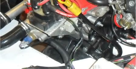 With the core plug I tried getting it to spin around in the hole by using a hammer and a screw driver. Didn't work. In the end I drilled some holes in it and used a hack saw blade to split it. Came out a treat then. |
Nice one thanks dave. Any idea what size/thread the hole was you drilled & tapped for the temp sender?
|
The Acewell sensor requires an M10x1.0 thread. I am not sure about the Sierra one. I think it will be a imperial possibly?
|
Ok so I managed to find the fan switch on the donor manifold but I'm struggling a bit with the temp sender. According to the hanyes manual it looks like it should sit to the left of the thermostat housing on the inlet manifold but mine doesn't have anything there. I'm guessing the pic in the haynes manual is for the carb'd cvh rather than injection one like mine. Does it look like a kind of nipple that screws in? If so what does the loom connection look like as I can't seem to find what connected on there?
here's what i think is the fan switch?  and the temp sender?  |
And here's a couple pics of the manifold so far :)
  |
What you have highlighted is the quick warm up pipe which woul have had a hose looping round to the other side of the engine. You need to go more to the left on the manifold. It shoul look threaded on the connection, but it is for a push on connection. Similar to the oil pressure warning light switch in the block of the engine.
|
Had another look this morning and I'm still struggling to find it. Came across this http://fordsierranet.com.ar/Fotos/En...%20systems.PDF and on page 20, it talks about the engine coolant temperature sensor being on the bottom of the inlet manifold (which mine has) and it then goes on to talk about it again on page 22 under the esc hybrid section and says its on the left side of the thermostat housing but mine doesn't look like the picture as I have an exhaust gas recirculation inlet there?
|
Below is a picture of the inlet manifold on Gus's donor. His finger is touching the sensor for the dash temp gauge.
Yours should be similar. 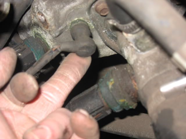 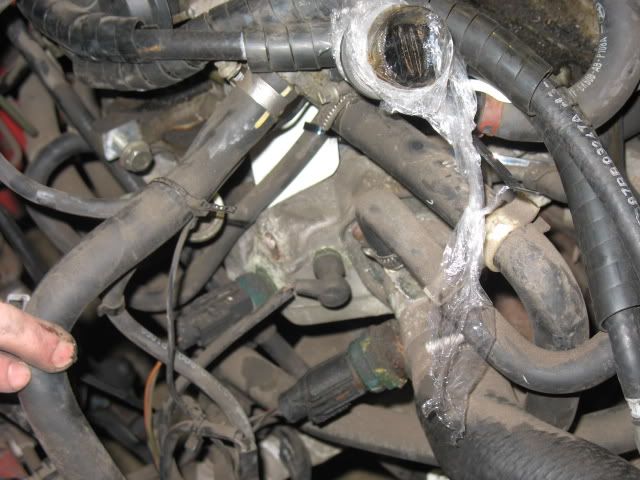 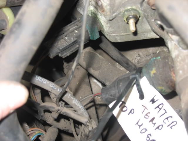 |
I wouldn't worry to much about the Sierra fan switch as it won't fit the FWD thermostat housing. You need one from a Escort or Fiesta that was fitted with a cvh. Something similar to the below. But a standard one would do.
http://www.burtonpower.com/xefs4.html |
Ok good to know, I guess the escort or fiesta fan switch will then attach to the fwd thermostat housing? For the temp sender, still a bit lost as mine doesnt look like gus's, if you look at this picture, you can see I don't have anything like that next to the thermostat?
|
Could be in a different place, but it will be on the manifold, and should look like the one pictured.
|
Ok so I approached this a slightly different way this time. Having seen your picture of the connection I found that on the loom and luckily I had numbered it when I took it off. Low and behold the same number was on the bottom of the inlet manifold so I took the bit out and it looks like yours although it doesn't have the same bit sticking out of the top. Does this mean mine is broken or just different because of it being an injection engine?
loom connection  position on manifold  and the part taken off the manifold   |
Also finished the manifold
 |
And had a play with the fan switch off my donor manifold. Turns out the 1.8 cfi fan switch has the same size/thread as the polo rad and the fwd thermostat so saves me buying a new one :) So I reckon I'll leave it on the fwd thermostat to plug the hole there and leave the polo fan switch on the rad to plug that hole and then just route my expansion bottle bottom hose to a T joint on the bottom hose rather than attempt making something to fit into the polo rad fan switch hole.
fitted to polo rad  fitted fwd thermostat   |
That's definately the engine tem sensor that you are holding in your hand :)
The centre part is missing ( Should look like Gus's ) No real drama there, you should be able to get a new one without any dramas. If you are going to fit an aftermarket Temp gauge the chances are that you will need to change that anyway ;) Pleased to see you managed to get your inlet manifold sorted :) |
Yup took awhile but got there in the end, bit annoying really that the haynes workshop manual doesn't really give much detail around the cfi engines. Just need to drill & tap a hole now for it in the manifold. Any idea what thread the temp sender should be? It looks close to an M10 but an M10 nut only screws on a little way before it stops so I'm guessing it's an imperial thread of some kind?
|
Hi
I got a sneaky feeling that it has a taper thread ( They quite often do ) ;) Will try & have a look for you later, it just so happens that I have a CVH manifold & carb on the workshop shelf & the usual sizes of taper taps :) |
thanks bonzo :)
|
Well I looked
Guess what, it snapped off :D :D Not all is lost though, I am almost certain sure that Ford use a 1/8th NPT taper thread for temp senders ( More or less an industry standard ) I guess that's why most el-cheapo tap & die sets have a 1/8th NTP tap in them ;) Here's an ebay linky, not going to break the bank. Ford Temp Sender |
Gosh that's cheap, I tried my local motor factor and they want £10 for one! So never having done a drill & tap before, what size should I drill the hole to for this before I try tapping it? (I've only got metric drill bits as well...)
|
According to my little Red book ( Osbourne cutting tool guide ) the tapping drill size for 1/8" NTP is 8.4mm :)
An 8.5mm drill bit will most likely do the job if it is a decent quality one ;) |
Is 1/8 npt the same as 1/8 npt27? I checked my tap & die set and I've only got metric ones so I'm going to need to buy one and considering this one http://www.ebay.co.uk/itm/24-Piece-U...em2 7b6c747b3
|
Hi
Yes according to my Red book a 1//8th NPT thread has 27 teeth per inch :) I have 2 or 3 of those, you are more than welcome to have a lend of 1 if you don't want to spend a pile of dosh on a tap set that might never see use again. Also got a good stock of 8.4mm drill bits, quite welcome to have a lend of one at the same time. Hope that is some help to you :) |
I might take you up on that bonzo, I'm going to check with the neighbor tomorrow in case he has one but if he doesn't a lend of one would be great :) Already had to spend a small fortune on coolant hoses so any money saved is good!
|
You will be most welcome if your neighbour is unable to help :)
|
Nope the neighbor didn't have one but I'm considering buying a set anyhow as I'll need one for the seat belts too and it's probly a handy thing to have for future use. Do you know what thread the seatbelt mounts is supposed to have? I think it was something like 5/16 but there seems to be more than one thread type when I look at these two:
http://www.ebay.co.uk/itm/US-Pro-too...em3 cbad6ca28 http://www.ebay.co.uk/itm/24-Piece-U...em2 7b6c747b3 |
Hi
Yes, the seatbelt bots are 7/16ths UNF/NF If you are creating a new thead for those the tapping drill size is 9.9mm. The exact reason I keep all of my imperial stuff here, tis surprising how often I have a use for one of em |
So which one is UNF/NF? NC12, NC14, NF20?
|
Some of the imperial thread sizes/pitches are a little confusing.
NC & UNC are both the same NF & UNF are the same The threads of the seatbelt fixings are most commonly called 7/16 UNF & has 20 threads per inch ( Also known as 7/16 NF20 ;) ) Hope that helps :) |
| All times are GMT +1. The time now is 11:54 AM. |
Powered by vBulletin® Version 3.6.4
Copyright ©2000 - 2025, Jelsoft Enterprises Ltd.