My steering column sits further back. As its meant too. You'll need to make an extension to reach the UJ. I'm going to look through my build photos to show how I got around it.
|
Quote:
(hope im not questioning too much:o ) |
Right, here goes, I'll try to cover it all for you.
The yoke that was posted in one of my pictures bolts to the large holes in the support frame. You'll need to use some largish & thickish penny washers to ensure a good fixing. At the bottom of the yoke there is a hole to take a Pinch bolt. This bolt passes through the two slotted holes on the underside of the steering column. Originally this would have been fitted with an adjustmet lever & plastic fittings to help lock things in place. You will need to fabricate some form of crush tube in order to bolt up tightly. Your steering wheel is a tad too far forward, needs to come back a little. The yoke & pinch bolt assembly should give you more or less the correct position. You need a new steering column bush kit for the large hole in the bulkhead, they are available on ebay for about £5 Once this is fitted the shaft will become quite rigid. Now, this is how I extended my shaft ....OOerrr that sounds a bit rude :D :D The section that you currently have connected to the steering rack is the piece I used. It was cut in half, I found some thick wall tube, cut it to the right length. I then welded the part that I cut in half to each end of the tube. As far as I can tell. That part is made of cast steel & welded OK. That said, as a safety feature, I will drill each end through & place a double roll pin in there. My shaft ended up just right & not too close to the chassis or any other components. ;) |
Yeah, mine (which is an adjustable steering column) sits with maybe 100mm past the plate. Then the 1st section of the cut UJ bolts on, then the extension tube (around 400mm I think) then the other half of the UJ, that goes onto the steering rack.
 |
the little plastic collar needs to go further up the column than how you have it at the mo, this then sits inside the rubber grommet thing that is held in place by the hole in the plate CP16, these are available for £4 off ebay if you haven,t got one.
i have a few pics of how i extended my column down to the coupling on the steering rack, i,ll find them & post them up. and no you are NOT asking too many questions, thats the purpose of the forum, i would be lost without the answers of the lots of questions i,ve asked. cheers andy:) |
Quote:
|
:eek: i,m too slow, precisely as the two above posts, thats how i did mine.
andy:) |
Quote:
|
Quote:
I really struggle to see where i would be without the almost instant help recieved from these forums;) . A BIG thanks to you all!!!! |
Heres a picture to give you a better idea :)
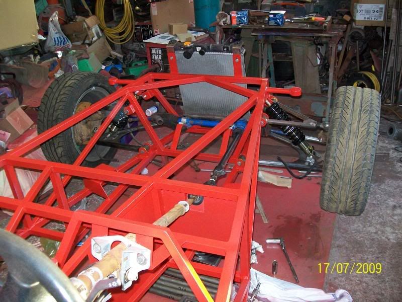 Best I could manage. Feel free to admire all of the mess in the workshop :D deezee I noticed that you did exactly the same as me ;) EDIT Before someone picks up on it, I know the safety washer has to sit on the plastic bush. I have a new one that I will fit during the final assembly. |
YAY... i fabricated a bracket for the steering and fitted that, i then spent some time trying to accurately measure the extension require and it came to just under 400mm extension. one thing that you may all object to me doing though is the fact that i used 25mm square tubing wiht a 2.5mm wall as that was the only suitable metal i had for it. There is a problem though, the extension seems to be hitting u2 and as it is square tubingwhen i turn the wheen when it gets to the right andgle on the edge of the square tubing, it pushes the extention away from u2., but it still turns freely, but it is touching u2, i can see from bonzos pic the coloumn is extremely close to u2, but mine is just about touching.
|
damn. just ran into abit of a problem, i dont have the keys atm, so anyone know how to disable the steering wheel lock without them:confused: :p :o
|
I'm afraid the only way I know involves a screwdriver and wrecks the lock.... misspent youth I guess.
|
Looks like you just had the same day I did.
It took me the whole day just to get the steering support brackets right, not helped by my total inability to calculate the correct angles to cut. I've descided that me and compound mitres just don't mix, but I have some excuse in that I've a MT75 gearbox so the transmission tunnel angles don't match what's in the book. I also saw some posts on another thread that suggested mounting the bracket on top of the top tube made fitting the side panels harder, so mounted it to the side of the tube instead. Out of interest, what have you made the distance from the centreline of the steering column to the centreline of the chassis? Matt |
Quote:
I measured the distance and along tr8 it is just over 250mm from the centre of steering column, to centre of chassis. Also for those interested i made the braket i threw out with some 3mm stip bent and bent it around the steering column and then welded and drilled some scrap 3mm steel around it.(also if youre wondering i will eventually get around to drilling holes for the :p pinch bolt(oh yeah and i will add some bracing in the bracket as well eventually)) 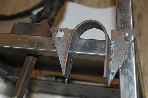 Completed steering bits: 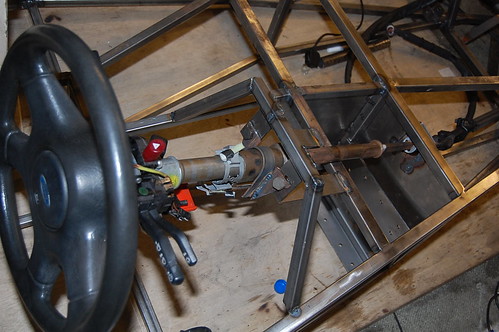 |
Maybe I'm being an idiot, or I've not read all your posts right, but isn't your steering wheel support frame not in the right place. My Haynes book isn't at home, so I don't know the tube name. But the one on the right side of the steering wheel support frame.... doesn't that line up to the outside of the rail?
|
Quote:
Matt |
Quote:
Also i will be putting some box section under the bit that is sitting on the edge of tr2 to support it. |
HI
Im now on my second roadster. I have put my supports as geeman. It saves cutting the scuttle close to the out side edge and stopping it from starring(cracking). Not a problem if you are making one form steel. |
steering support
hi guys
yes that is exactly what fabby recommends and then brace it with a a bit of box in the area just below the the blue disc in geemans picture cheers geeman that has really cleared up what i was trying to put across in my previous post cheers les g.. |
Quote:
|
Geeman....
can i ask.....why is there a gap between your pedal box plate & CP16 ? as from the photo it looks like there is a gap ??:confused: cheers andy:) |
youre right there is a gap in the photo, but it isnt fitted in place. i must have just left the pedal box plate in place there as i was checking if it fitted earlier today. it does go flush with cp16.
Thanks on a completely different not, i applied for my provisional liscence today as i will be 17 in september and can drive in not too long !! :) |
sorry, wasn,t trying to be a pain
i just didn,t want you to tack/weld it in place like that, as obviously you know it fits from slotting it into place from the engine bay side :cool: it looks like the pedal box is from 3GE, that,ll fit no prob, :cool: nice one going for your license, you,ll be 17 in september makes me feel REALLY old :eek: i,m 29yrs ahead of you :o once your Roadster is finished you,ll be able to drive it on private land or on the road when insurance is sorted, sounds like a good excuse for a track day eh??? all the best andy |
That's it, makes your life easier when fitting the scuttle as no need to take a big chunk out of the base to allow it to fit. Also helps with the sides whether using grp or ali...I used to use two bits of 1" diameter tube welded onto the inside rail then made a hoop in 3/4 diameter tube, plop that into the 1" diameter tubes and angle it to suit then weld it up....neat and very simples:D
|
Quote:
|
Hey Jas, have you started your own website for electrical stuff, or has you address book been hijacked?
It looks like it was sent by Ali G (no relation to Ash! :D ) vHey, how are you doing recently? I would like to introduce you a very good company and its website is www.welt188.com .It can offer you all kinds of electronic products that you may be in need,such as laptops ,gps ,TV LCD,cell phones,ps3,MP3/4,motorcycles and etc........ You can take some time to have a check ,there must be something interesting you 'd like to purchase . The contact email: welt188@188.com MSN: welt-188@hotmail.com TEL: 0086+15110177918 Hope you can enjoy yourself in shopping from that company ! Regards I Regards John |
ok.. well as i couldnt ge tthe front wheels on today, i thought id try fitting some engine and gearbox mounts. i got the engine in the chassis relatively easily, but i had to cut out tr as i can imagine the engine fitting with it in place. my next problem is that the steering coloumn wont reack the rack as the mont that is on the engine gets in the way of it. I have a 1.8 cvh and wondered what the mounts are meant to be like for it, as the engine wonot go low enough for the steering column to be at the right angle to reach the steering rack. any suggestions for those who have a cvh??
Ill try and get some pics later to better descibe my problem. Thanks |
Unfortunately I havent had the time for anything like that John!
Indeed I have been hacked/hi-jacked:eek: Teach me for using the same password everywhere...:o Cheers For the concern matey! |
Quote:
You may find that you will need to fabricate your own custom mounting arms to avoid the need of re-routing the steering shaft ;) If you want a bit more freedom to be creative with the engine mountings. You can pick up some landrover rubber engine mounts on ebay for about a Fiver. A lot less bulkier than the Sierra ones & more than up to the job. :) :) |
Here's a picture that may help give you some ideas :)
 That's a Land Rover mounting rubber I know I am using the Zetec engine but by chance, that side of the engine block is the same fitment as the CVH ;) I have left it tacked up at the moment, i'll probably re-make it when i get some thicker wall box section :o |
ok, thanks bonzo, i was hoping it wouldnt come to me having to make my own bracket, but i guess ill have to. Did you also make your own bracket on the other side or keep the one that was on your zetec? i would have made the brackets today, but i went into the garage, was about to wheel the chassis outside, it started raining so i couldnt be bothered really. :rolleyes:
One other thing is how far in do people with type 9's maake them sit. im wondering how far in it should go. Today i welded up the front lower wishbones and so now nearly have a complete set of wishbones, just need to weld the shock bracket on the wishbone. Ill put the wheels on tomorrow on the front and hopefully make the engine mounts soon.  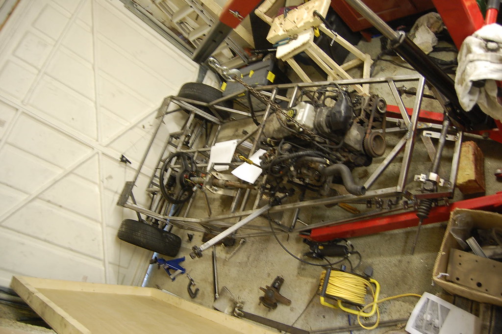  |
Hi geeman,
i,m using the 1.8cvh engine & i also had to make up an engine mount for the drivers side so as to allow the steerong column to fit, i used the original ford alloy mount for the passenger side & used the original rubber mounts on both sides. i can post some photos later tonight of engine position etc, as for the gearbox position, basically you can use the reversing light switch on the drivers side of the gearbox as a guide to the forward post tranny tunnel upright next to your left leg (sorry haven,t got the book with me). the gearbox position then dictates the engine position. if you look in the thread "big day" in the chassis section there are some photos of my engine/gearbox fitting. cheers andy:) |
Quote:
 do you have a t9 or mt75? ALso could you get a pic of where the gear lever would go so i can see where abouts that is in the transmission tunnel it sits. ive also for the past few days successfully resisted the urge ot sit in it and make silly car noises.:rolleyes: Thanks!! |
Hi, yes sorry i should,ve mentioned that rail needs to be cut out for when you fit the carb & manifold etc,
i,ll get some photos of the gearbox/lever position for you later. go on.....sit in it & make some funny noises, you won,t be the first or the last to do that :D :D :D cheers andy:) |
sorry, forgot to say........i,m using a type 9 gearbox.
andy |
here,s a couple of pics to help with your engine/box install,
sorry i haven,t got any showing the gear stick position but these might help.    sorry that the first pic is a bit fuzzy, but you can see the position of the engine. cheers andy |
Thanks for those pics, it made me realise why i couldnt get the engine to fit just right. I completely forgot to cut out the bit between the u7 and u6 uprights in the chassis:rolleyes:. No wonder the gearbox wasnt going in all the way:o ! im just laughing at myself right now as i spent half a day standing about thinking why the engine wouldnt go in fully and only just realised that i forgot to cut that bit out:p . hahaha, i cant stop laughing at that:rolleyes:
|
i imagine a few swear words were uttered eh??? :D
glad the photos have helped ;) :) sometimes it helps to stop when you hit a "problem", take stock of whats happening & sit down with a cuppa & read the book again. ;) andy |
Quote:
i think my lack of sleep and constant smell of buring paint and oil and inhaling too much argon is finally getting to me..... :rolleyes: |
| All times are GMT +1. The time now is 09:47 PM. |
Powered by vBulletin® Version 3.6.4
Copyright ©2000 - 2025, Jelsoft Enterprises Ltd.