Hi,
Hello John.... Not OCD I'm afraid just too much time on my hands....:D Yellow looks nice from a photo but in reality I wasn't happy with the finish as I didn't origionally put enough down so I thought once everything was mocked up I'd put down a heavier coat once I rubbed it down. Lot happier with the finish now almost like powder coat.... Well with regard to the ISCV take off I was thinking of using a "Revotec Self-sealing Hose Fittings - For Water / Air Hoses" in 19mm and place it between the throttle body and air flow meter hose using silicone hose elbow somehow. Do you see a problem with that? In the worrkshop manual it states it controls "Bypass air amount". I guess it checks the amount of air flow before and after the throttle body sensor. I'm not upto speed on the MX5 (or any other car for that fact) so I was hoping this was going to be OK... Hi Wgroove, Thanks for that. I'm using three ply polyester reinforced silicone hose used for cooling or air systems. It's a bit decieving in the photo as the top coolant hose is two pieces but as yet I haven't fitted my hose clips so it looks as though it is one piece. Hopefully the rest of my order will turn up soon so I can finish it and post a piccy. Well I hope I've been of some help ...Johno:) |
Hey Johno, those Revotec jobbies look perfect!
Wish I'd known about them earlier - my current solution involves various hoses, joiners, and a horribly convolted path :rolleyes: |
Hi John,
Glad to be of help....:) God knows how many times you've helped me out probably without knowing so I'm only too happy to be of some use....:D The're a bit expensive but it gets over the problem I hope.... Johno |
Sorry forgot to say,
Found them on "Europa kit car parts website" for about £19.95 so was going to order one today to see if it worked out. Revotec was a bit dearer I think.... Johno:D |
I think I saw them for £25 when I googled for them earlier :eek:
To be fair I've probably spent that on the various bits I got to do it, and I'm a bit reluctant to spend it again! I think I can just about make what I've got work, but it's nice to know they're available as a back-up plan! |
Hi Johno
Great to see some more cracking progress pictures. :) :cool: I love the engine in its new livery :cool: May I ask what paints have you used as it looks to give a cracking finish ? |
Quote:
I've used "Alpha coatings" VHT paint on engine and gearbox and Polyurethane on the cam cover and inlet manifold. I asked my local bodyworkshop/refinishers what to use throughout the build so if it's wrong I'm buggered.....:eek: These guys have been supplying paint to most of the bodywork shops around here for years so I guess they know what they are doing.... If it doesn't work out I guess the olde orange sandblaster will see the light of day again...... Johno |
It all looks really neat. If mine turns out anywhere near as good as that I'd be well chuffed :)
|
Hi,
Thanks Dave I'm sure you will do a great job of your car (where you upto, need some photos). Well John I got my Idle valve connected to my air inlet and seems to be OK, just hope doing away with the various plastic bits will not do too much damage....:eek: It's a bit of an expensive way to do it IMO but here it is..... 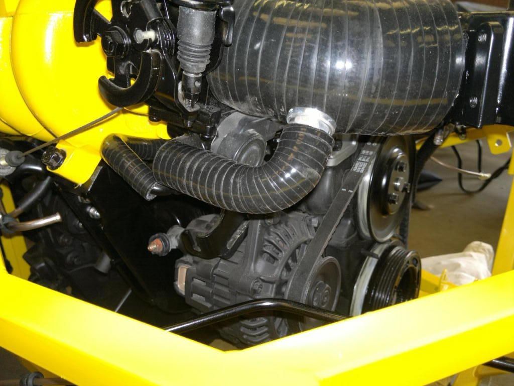 Not done too much on the car this week as it's been too bloody hot..... plus now the rains stopped I've got to tackle the "Triffids" in the garden...:mad: Johno |
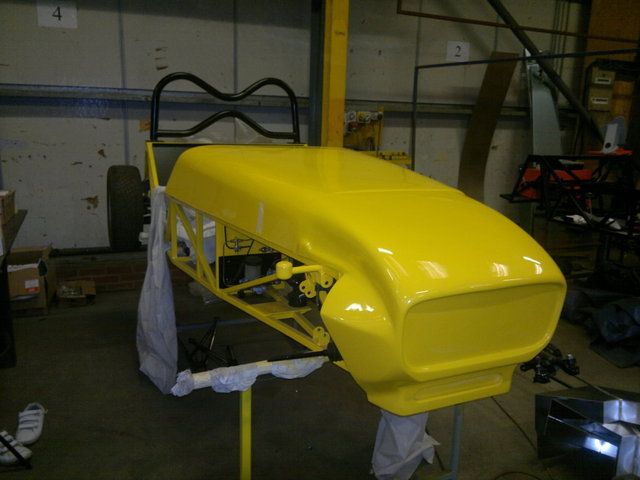
Decided today to go with my original roll bar. I was in two minds about it but it's what I planned from the start and she's been sitting there for some time so I welded her up today and gave her a clean up and some paint.:)
I think I might make a standard one for the IVA later on just in case it hampers the rear vision. Also sand blasted my various track rod ends and ball joints etc.... and gave them an undercoat at the same time. Here she is cleaned up before painting... 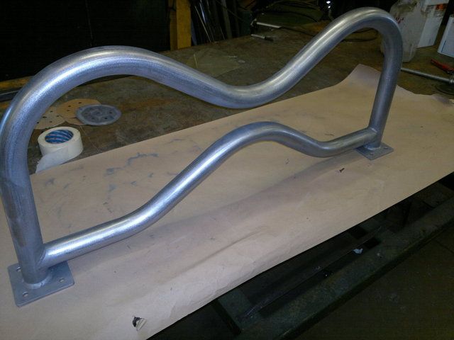 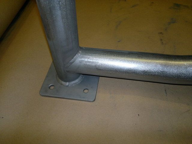 She's had a couple of coats of acid etch primer and a few coats of grey primer now so tomorrow I will be able to rub her down and give her a top coat if all goes well......:D http://s1199.photobucket.com/albums/aa472/JohnoSS1/ Bye for now.....Johno |
Well I got a few things done on the car in the last week.
I managed to paint my roll bar in the end after making a mess of the first top coat... then when it did go OK a bug decided to do a "Kamikazee" dive straight into the nice wet paint... well I guess thats the first of many to end their life on it..LOL Installed my clutch cylinder piping, all I need to do now is purchase a flexi hose to go between the "T" piece and slave cylinder. I've tried to keep the pressure switch low on the "T" for my brakes and clutch to help prevent air being trapped between the oil and the switch. Finished my throttle cable routing and connected it to my accelerator pedal. The pedal just needs the stops adjusting now it's all in place. Finished my top and bottom rad hoses which now need clipping up. Is it better to use the constant tension clips for this job or will Jubilee's be fine? Fitted some silicone hose to intake manifold and various components. Sand blasted ball joints and gave them a few coats of paint. Started painting my internal panels. Also the steering rack got a coat of paint. Clutch "T" in place with hard lines... 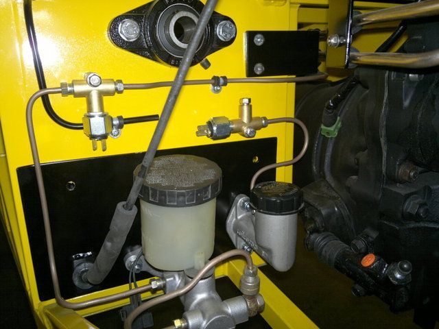 Bottom coolant pipe with bracket welded to it and fixed to chassis... 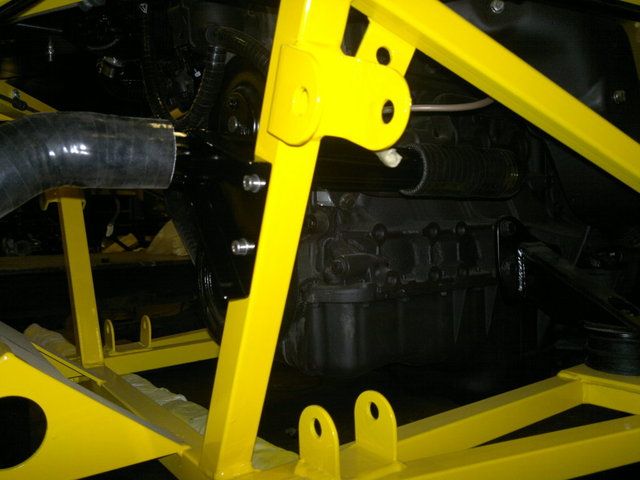 Roll bar and some of the internals panels in position... In the background is Simons build with a hint of Orange here and there. 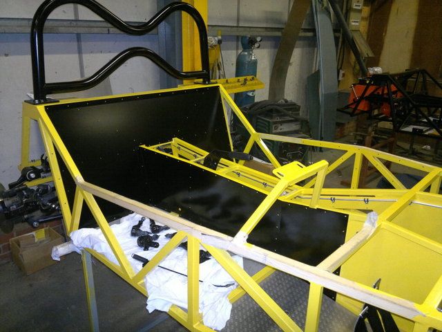 New silicone hose on some of the air intake manifold fittings... 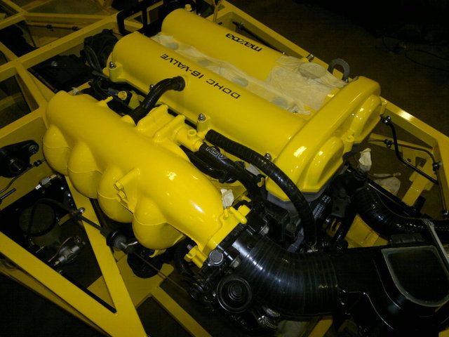 http://s1199.photobucket.com/albums/aa472/JohnoSS1/ Johno |
totally awesome work Johno I really need to get some darker shades....nobody is gonna miss you in that dude....keep it up mate, keep it up (the work I mean:p )
|
You have been a busy boy Johno!
What's the travel like on your throttle pedal? |
Quote:
I'm trying to darken it a bit with all the black panels and other stuff I have planned... Hi John I took a couple of photos of my pedal travel, why do you think there is a problem? 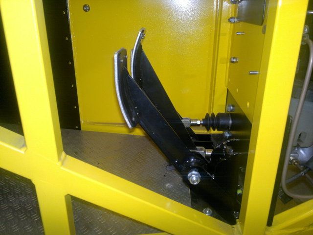 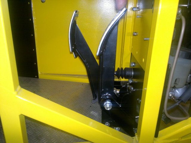 There is a fair bit of adjustment with the standard cable setup just before the throttle boddy on the original MX5 cable.... You got me worried now... On the down side of things you were right about the amount of steering lock. I have the same problem as you regarding as the extension hitting the wishbone.....bugger... Like yourself I am going to fit some sort of steering limiter which will help with the self centreing for the IVA. I've had a look around and there is nothing for the Ford Escort steering rack but there is kits for the Ford Focus with 18 inch wheels and Fiesta I believe. MNR fit a 5mm wheel spacer to the hub to stop the steering ball joint hitting the rim. I was thinking of getting a ally spacer bush made up in two halves with a jubilee clip to pull the two halves together. Each spacer would have a lip to just clear the jubilee width if you understand what I mean. I was also thinking about altering the extension itself in regards to thinning it down a bit with the MX5 ball joint only being 12mm thread. I will see how that goes. Out of curiousity how wide were your plastic steering rack stops? Johno |
Does that give you the full range of movement on the throttle body?
My pedal travel seems to be a lot more than that, in fact it's slightly rediculous :rolleyes: I'm thinking I might have to extend the bottom of the pedal down to give the cable more movement for less pedal travel if that makes any sense. I can't quite remember how wide my rack stops are. They weren't much wider than a jubilee clip though, maybe 20mm or so. Going to stick with that solution, but possibly remake them out of something less likely to shatter. |
Wow johno looks really good if mine come out half as neat I will be happy keep it up mate
|
Thanks all,:D
That's full travel on the throttle body John. Simon was with me when we adjusted it today to see what we could achieve. The accelerator pedal is book spec with the only addition of a home made clevis arrangement to accomadate the original cable. What sort of travel do you have then? I can't see why you should have a problem...... do you have the ability to alter the the lenght of travel near the throttle body? Johno |
Well I altered my rear top wishbone yesterday.
Forum member Robo made a valid comment on them some time back and I've only just got round to altering them. At the time I made the adjuster out of 18mm coarse pitch studding which was OK for mocking up but no good for road use. After I made them I was not happy as I knew that thread in a shaft was not a good idea and Robo's comment only reinforced this. Basically he said "think Tobelerone" which is a good perspective as the coarse thread pitch along with thread all the way along the adjuster was a bad idea (failure everywhere). Well I wanted to keep the top adjustable wishbone idea and tackle the adjuster...... Here's my latest version.....:) I started off with a 18mm fine pitched bolt rated at 8.8. This had the head cut off and a thread machined the same end... 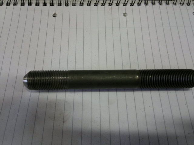 The part of the bolt which was to be welded to the yolk was prepped for weld. The yolk was also uprated to a 10mm back plate with 6mm side plates. Before the bolt was tacked to the yolk a Stainless half nut was fitted along with a machined half nut. The bolt was then welded to the yolk. The machined half nut was then welded to the back plate once it was tightened as far as it would go.... 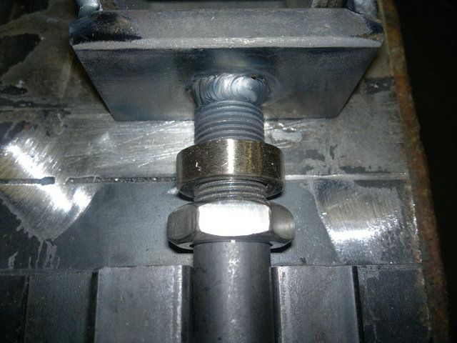 Here is the finished result... 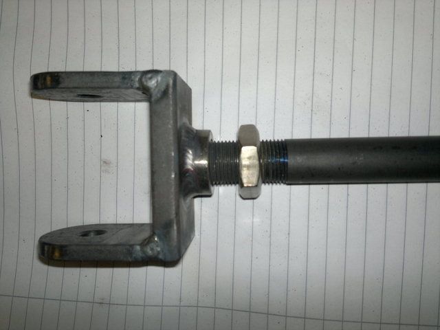 The idea of the machined nut is to reinforce the bolt along its length without putting another weld further along. This will also help to strengthen the weld under the machined half nut without creating a further failure point. Well that's the idea behind my thinking. The amount of thread between yolk and wishbone is quite small so hopefully this will help as well. The shank of the bolt is now inside the wishbone which gives a lot better fitment and strength. I'm more happier with it now but if anybody has an issue with it please let me know.... Thanks Johno Will post a picture tomorrow of the finished item... |
Stop posting the welding porn, puts mine to shame :mad:
Your build is coming on brilliantly, I can't wait to see the final result. |
Nice fabrication, but actually it would be more convenient to use rose joints. AshG has done it on his build years ago beautifully with quick adjusters. Samples are on his photostream.
|
Quote:
Sorry Steve will show all the welding posts from now on with an 18 certificate ......:D Trust me there's a lot of better of welders on this forum than what I can do....:o Yeah I can't wait to see what it turns out like too as I'm making it up as I go along now....LOL Well here's a photo of the finished adjuster painted and in place... 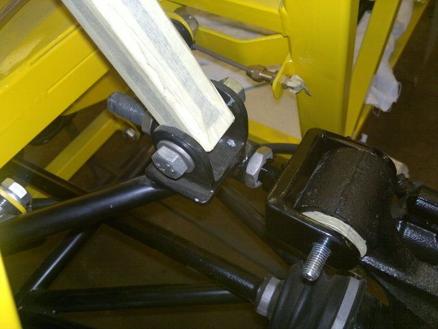 Just got to add a couple of washers and a nylock to finish it off and it's done. Well I guess it's the wiring loom next and it's routing which I'm not looking forward to. Bye for now....Johno |
Quote:
Well I like doing things the hard way..... At least i can say I made that (unless it fails and it's somebody else's fault):D will see how it works out :) Johno |
Quote:
It would appear Nathan at NTS had supplied me with a Sierra clutch pedal instead of an MX5 throttle pedal! I suspect it might be a bit late to get him to swap it now he's dissapeared off the face of the earth... :rolleyes: |
Hi John,
Glad to hear you found the problem...:) I don't have the book with me but I guess the clutch pedal is shorter below the pivot bush? Should be an easy fix them as long as the guide tube through the pedal box still lines up with new position of the throttle connection. I've not done too much on the car lately. I've tried to spend some time with the kids whilst they're on holiday. I have drawn up an alteration to my current rear top wishbone. The lower mount for the shock is now above the yoke. I'm hoping this will put less stress on the adjuster. It's now similar to the Sierra setup in configuration. The position of the lower shock mount is 25mm longer than Saturns plans. 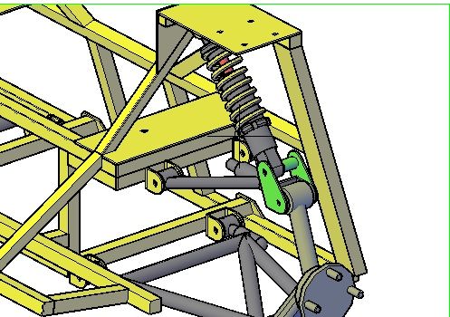 Also when the car is at ride height the shock and top upright pivots are all in line as you can see in this drawing. 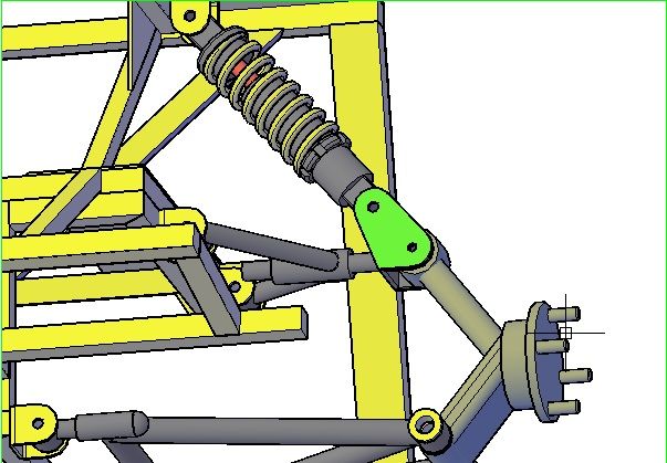 This means I've just got to modify my yoke and i guess the shock will need to be 25mm longer..?? What I am trying to acheive by doing this is to use the lower adjusters on the bottom wishbone for "Toe in and out" and also track width. The top will be purely for "Camber" adjustment as I can do this in situ without removing parts. I should be able to get fine adjustment because of the fine pitch thread of the bolt. Does anybody see a problem with this?? as it's only on paper yet. Thanks Johno |
I would say thats a sensible mod, You are taking a lot of strain off that top adjuster.:cool: I dont suppose moving the spring outboard like that will foul the inset of the wheel rim on the mazda set up would it?
Bob |
Quote:
I'm glad you think it's a step forward. As you said in a previous post it had flaws. :eek: I'm hoping the bolt now will be OK. I don't know if you have seen my previous post but I modified my design of the yoke and adjuster. It's now an 8.8 grade bolt with the head cut off and fine pitch threads both ends with the shank of the bolt in the body of the bush. The bolt was chamfered for welding and and a threaded collar screwed onto the threads before welding. The bolt was welded to the yoke and then the collar was screwed upto the yoke and only welded to the yolk and not the bolt. My thinking was that this would not put stress directly on the weld between the bolt and yoke as the collar would help transfer some of the stress further along the bolt. Also there is minimum bolt length between the yoke and the bush. Sorry to bore you all...:o I believe the clearance between the wheel rim and shock mount should be fine but as of yet I haven't checked this on the car. Looking at this photo it should be fine.. 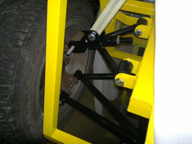 I'm not sure but doesn't the Sierra rear top wishbone have a similar setup in reference to welding a bolt to the bush..? (books at work). Also I'm sure I've seen a picture of a yoke welded to a bolt in the book for use on different donors. Well thanks for the input Robo I always appreciate advice from you guys. Johno |
Westfield bring their shock straight off the top of the rear hub
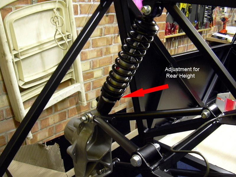 The thread thing makes me nervous because a friend of mine built a v8 rover westie and the top rose joint sheered of. Westfields answer was to send him a better quality unit. Kin great when it could have killed him.I was in that car at break neck speeds the day before.It was not the one with the arrow that failed it was the top one:eek: So thats what makes me anti anything with a thread on it being in sheer. Thats why I will be doing the same as your lower wishbones but top and bottom on all four corners. All those are just under compression or stretch which would make me a happy bunny.:) 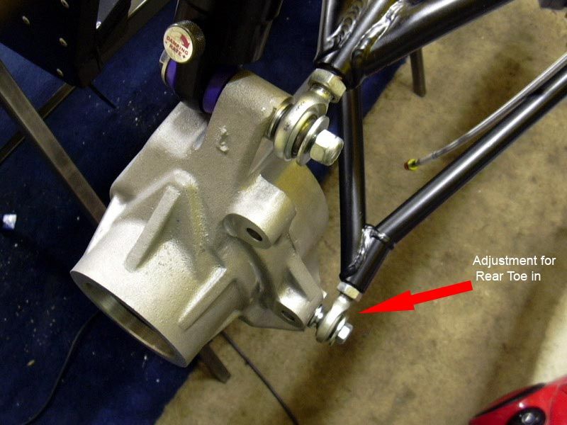 Bob |
Ooooooo scary...
Wouldn't like to be in that when that gave way (brown trouser time comes to mind). So if I'm reading this right Westfield do not always use "Top of the range parts" in areas of their build. Worrying that especially in such a critical area.:eek: I read in Keith Tanners build the company that supplied his chassis also supplied lesser quality parts and suffered suspension problems later on. Now you told me about that failure on your friends car I'm considering rethinking my rear top wishbone (currently MK5 I believe...LOL). If I do it will consist of inboard "Heim" adjusters and the shock still above the top upright (this time gonna ask for your opinions before fab).:D :D Unfortuneatly it's too late for my front lower wishbones (redisgned them and fabbed them...ohhh). 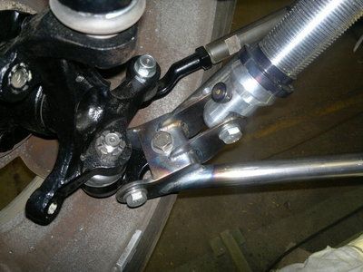 I chose to make new lower wishbones to give me clearance for my steering rack extensions when on full droop. Kept the pivot and shock mount points the same just lowered the tubes or "A Arms" (tryin to make "Old Jag Guy" feel at home).... Front tops are redisgned on paper but not fabbed yet. After reading "Alga's" post on "Self centrering" I'm not sure if I should move the threaded adjuster to the rear of the car more? I've designed them so they can be adjustable without removing the top ball joint from the upright. Will post a picture when happy with the design. Johno |
Bloody hell johno, its just taken me an hour to catch up on your build diary. You certainly have made progress and its looking better than ever! Love all the modifications, it wont be reconisable as a "haynes" soon!!;)
Stunning mate keep it up. Skov, Just stuck a pedal plate/tube/crush tube in a jiffy bag, cant beleive i did that aswell. I dont have access to a welder at the moment as someones got mine so i havent welded it. |
amazing work! Wish someone made fully adjustable wishbones for the standard Roadster's that would save me a heap of trouble with getting my setup done.
|
Quote:
Bob |
Quote:
Would it be possible to use a larger sized rose joint and fit a machined bush to bring down the size of the hole for the bolt? Johno |
I think your right. If the reducing bush was spun up with a large flange/washer as an all in one unit on the outside it would contain the joint in the event of failure.
bob |
Cheers Nathan and Eternal.
I'm just making things up as I go now and if don't lke it I change it..:eek: I just got to stop painting stuff before I'm happy with it........:mad: Robo did you have a look at Mcgill site, they seem to do a large range of rose joints and accessories. They also do M16-M12 Rod End Joint Reducers, High Misalignment spacers. Well I welded up my new front lower wishbones Saturday and this evening I tacked in a cross tube similar to the rear lower wishbones. I've decided to do this instead of a plate between the two tubes. So what I'm asking is this a good or bad idea? This time I'm asking before I go and weld it... 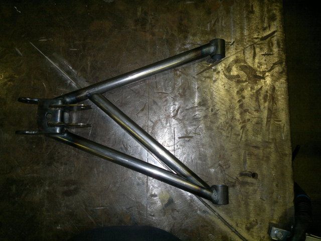 Whats you opinion? Photos updated http://s1199.photobucket.com/albums/aa472/JohnoSS1/ Bye for now Johno |
I think its a good idea, especially if you add another one crossing it going the other way. Whenever iv seen failed wishbones it has always been at the end of the plate. Must have something to do with the amount of heat the seam weld on both sides does to the steels integrity.
Ive read a while ago, something to do with wishbone tubes should not follow the exact path of any force going though them, cant remember where or what exactly, maybe a real engineer will come along and put me right or wrong.:D |
looks good johno. ive been following yours ( and skovs) build threads, even although ive been flat out with work for the past 5 months and done nothing to my car. i like the idea of your revised wishbone. im thinking of rose jointing all my wishbones and doing away with bushes etc. not sure if its a fantastic idea though?! haha
|
Hey johnno did you clock the upper wishbones on the roll bar thread. Thats the sort of thing I had in mind.
 Bob |
Ok you may want to put some shades on for this so be warned because here she is......:) :)
 I warned you...LOL Seriously need to tone it down somewhat with some black bits here and there I think. Very pleased with the panels just needs some more polishing in places. One bonus is the bonnet clears the engine even without a bonnet bulge and still needs to go up another 2mm for the side panels as well.:D I've just got to figure out a starting point to fit them from which I guess is trial and error to start with. One question, what's the best way to cut the hole in the front nosecone for the rad and oil cooler to achieve the best finish? Bye for now Johno |
Quote:
Haven't seen that thread but will look. Is this what you plan to do on your front wishbones as the American Locost boys use this type of setup as well and seem to have no problems. I guess this gives you some adjustment on your caster to help with centering right? I like the idea of that especially with the ability to alter camber without removing the ball joint. I've came up with a neat (hopefully) solution similar to the photo regarding camber adjustment for IVA and was also thinking about using Heim joints for caster (after Algas thread) but is it ok to mix and match poly bushes with Heim joints as my front lowers are poly now as below..... 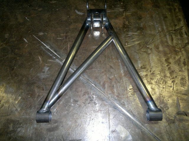 Cya all soon Johno |
Quote:
Yeah I keep playing around with the wishbones until I come up with something that I'm happy with....:D Check out LocostUSA forum, these guys only seem to use rose joints (heim joints over there) and seem to swear by them. So I would say if you want to go that route it would be fine.....:D :D Johno |
| All times are GMT +1. The time now is 04:03 PM. |
Powered by vBulletin® Version 3.6.4
Copyright ©2000 - 2025, Jelsoft Enterprises Ltd.