Quote:
Sorry I don't mean to depress anyone...:o Trust me John it's far from perfect (I only post the good bits...). Once I figured out what to do the wheel arch panels weren't too bad to do. I jig sawed the two sides plates and fitted a spacer to keep the distance correct and then tack welded a 3mm strip to the radius on the car. The awkward part was to stop them distorting when welding, for this I made some thick steel radius plates and clamped them inbetween the two ally sides and left them in place until they cooled down a bit. I still may bugger them up yet when I try to match them to my rear panel....:eek: |
Johno,
Have you thought about where you will source you aero screen from ? David |
Quote:
I looked into a supplier some time ago... Lo all, Had a quick look on the net last night and found this company, http://www.aerodynamix.co.uk/index.html that make various aeroscreens in carbon fibre and GRP. I emailed them last night to see if they fit the Haynes. The reply said they have supplied some to Haynes builds and haven't had any problems.. They certainly look good and also make other carbon parts... Hope this helps....:) |
Well I've eventually got round to start installing the wiring loom..
I removed the obvious stuff before placing it roughly in position in the car. I then set about removing some of the wires from the steering switches and fuse boxes etc.. which seemed easier to visualize what goes where when it's in the car rather than on the floor.. I've fabricated a shelf under the scuttle to install all the relays, wiring, immobiliser and ecu, to this shelf I can securely fix brackets to hold the various components in place. Here is a picture of the wiring roughly laid out in place. In the background you can see the ecu already mounted in place. 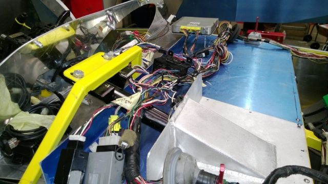 I've also fabricated a cover to go from the shelf to the underside of the dash which is removable. This will keep the electrics unaccessable to the interior of the car when the cover is bolted in place (you can just see it holding the dash in place without the scuttle). I've got other things on the go but don't want to give too much away yet. |
Well I think I've got the worst of the electrics out of the way....
It's been a bit of an uphill struggle to say the least. Colours different to diagrams, wiring modified and relays removed to say a few of my problems. All the wirings roughly laid out in place except the wiring to the rear (which should be straight forward now), just needs tidying up. 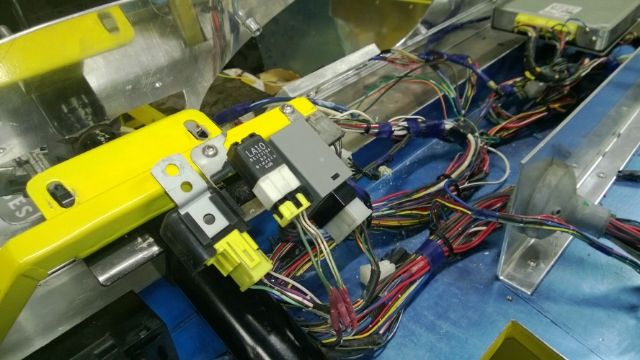 The main fuse box will be mounted to the removable cover for my steering column/brake pedals and when this is removed you will be able to access the secondary fuse box without removing the scuttle. 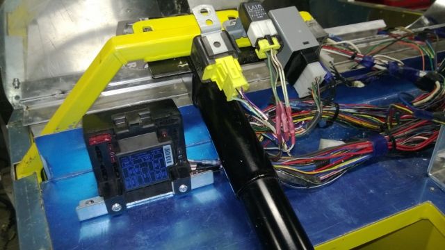 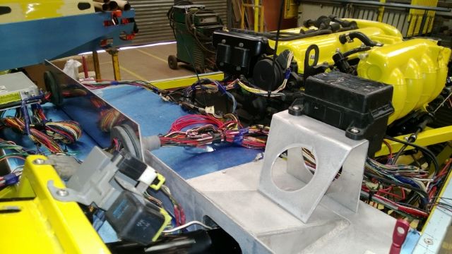 Hopefully within a week or two I should be able to try and start her....:eek: |
looking great you have some nice ideas that i may steal :D lol
|
Thanks thailoz, steal away buddy that's what this site is all about.
Well I fabricated an expansion tank today out of ally and raised it as high as I dare. It's approximately 200mm high by 100mm diameter with a 0.9 bar radiator cap which should leave plenty of room for the coolant to expand. I'm hoping I got it right but if anybody can see a problem with it please let me know as it was a spur of the moment thing..LOL 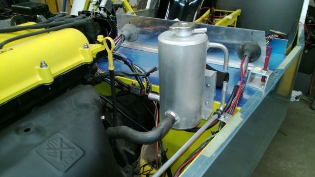 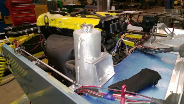 I've run a 10mm ally pipe from the top of the rad to the top of the tank which I guess should eliminate trapped air.. 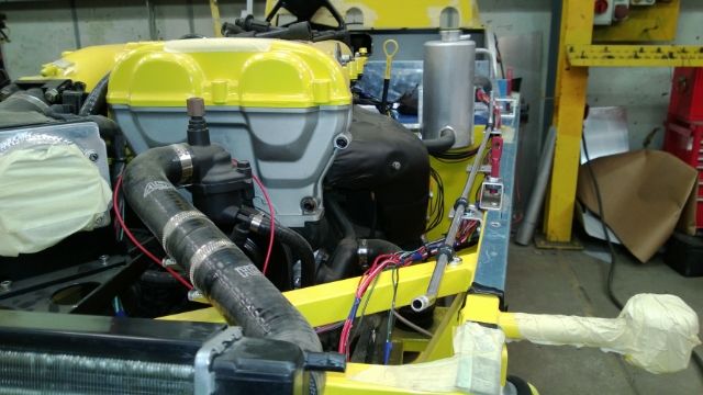 Just need to order some coolant hose to plumb it all up now. I've also been working on my electrics today and have the main fuse box in place and now routing the wires to the rear. 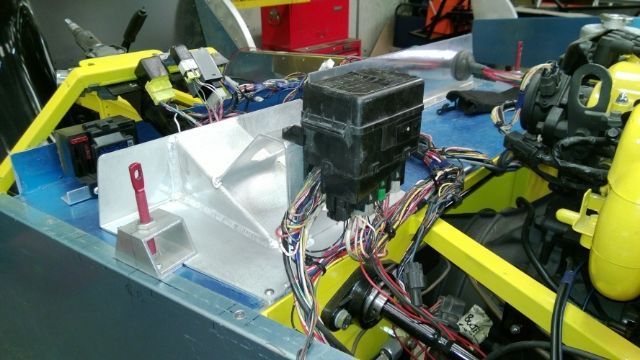 |
Quick update,
Fabricated my battery box tonight... 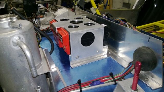 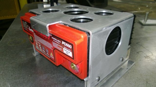 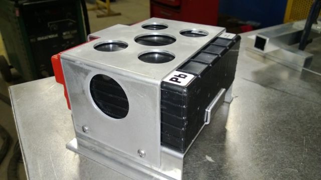 |
Nice box, are you going to put some U-Trim on it to prevent possible chaffing of the cables . Mr IVA may pick up on that.
Cheers TT |
Thats a classy touch Johno..... gonna be one very tasty build when complete :cool: :cool:
|
Quote:
Quote:
|
That battery box is totally wrong for the car, can I buy it:p
The nuts:cool: Bob |
Hi all,
Cheers Robo, it was just a spur of the moment thing really. To my surprise it only took about 1 1/2 hours to come up with the idea and fabricate it. Well today I modified my fuel tank to take the MX5 tank vent. I decided to raise it a bit on the tank with a left over bit of pipe to try to keep it out of the fuel. 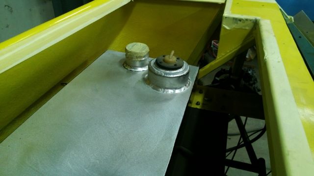 Also started making my back boot lid out of ally. It's rice grain effect chequer plate which has a lot smaller raised foot print. 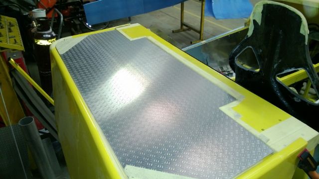 Also been looking at doing something different with the back end. Not too sure yet but when everything is black I'm thinking it will be Ok. It's nowhere near finished yet so time will tell...... 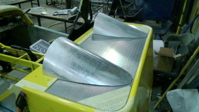 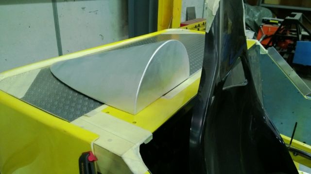 |
Quote:
Got my battery box cover back from powder coat last Friday and it's not looking too bad. I've had it powder coated in chrome effect...:) I'll put a photo up tomorrow.. Got quite a bit done on the car but also waiting for parts which are holding me up... |
Bat box is well cool ....certainly shows off your fabrication skills, and before you know it the yellow peril will be zooming around the flat lands of EA :D :D
|
Just a quick update,
I got a few parts back from powder coat last week and I'm quite happy with them. Battery box and expansion tank finished in chrome effect.... 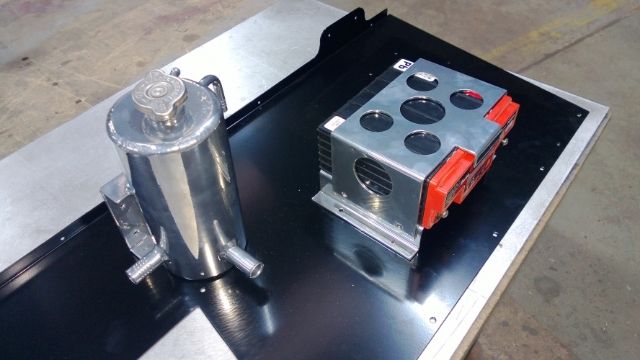 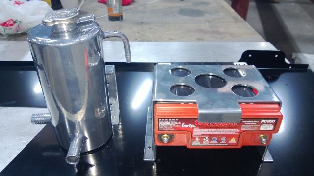 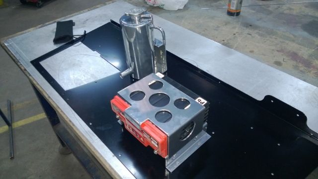 I'm now starting to put the car back together again with finished parts which feels nice....:D |
Quote:
Can't wait to get it on the road but got a long way to go yet...:( Things are now starting to come together but haven't started the engine yet....:eek: |
Some progress......
Spent a few hours on the car this week and still trying to sort my electrics out...:(
It seems to take an eternity to shorten and reroute all the bl**dy wires... and try to make them look half decent. So I decided to bolt a few things on to make me feel like I'm making some progress... 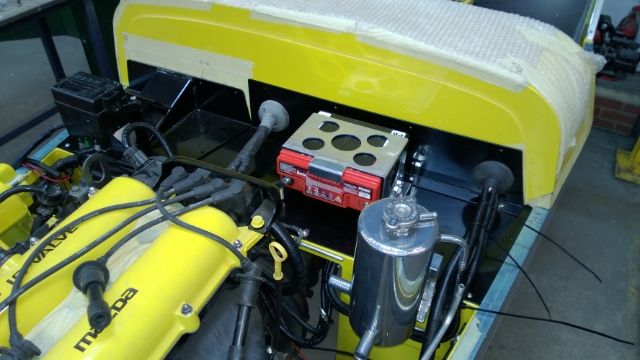 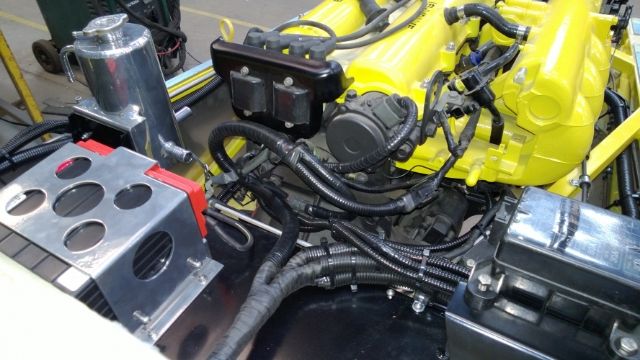 |
Johno your build is looking great.
Have you thought about the routing of the speedo cable yet? David |
Quote:
Well I'm hoping it shouldn't be too bad... I've got the 90 degree Toyota adapter on the gearbox to avoid the cable being bent too tight against the frame. With any luck should be able to try it this week as I'm trial fitting my dash at the moment... 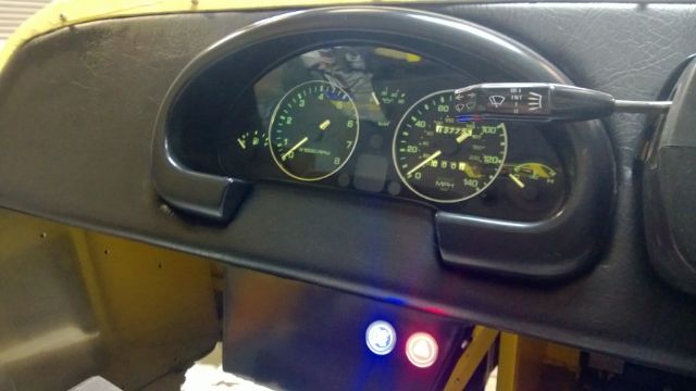 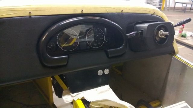 It's looking a bit tatty at the moment with the wrong type bolts holding the dash in place and all the masking tape still covering the GRP.. |
Quote:
Johno, I have got one of those 90 degree bends as well. I may have to add a small bubble so st speak to the transmission tunnel panel as it will be very close. i can see it banging all the time and not sure if the iva man would like it touching. *** Please could you also measure the distance from the centre of the rear wheel to the front of the rear wing. I am looking at putting my exhaust in place and dont want it to interfere once the bodywork is attached.*** Thanks David |
Hi David,
Would like to help in the exhaust dept but rear wings not fitted yet...:o Do you know which kit you are going for yet? |
Well it's time I posted a progress update I guess.
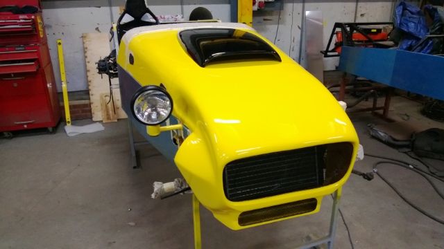
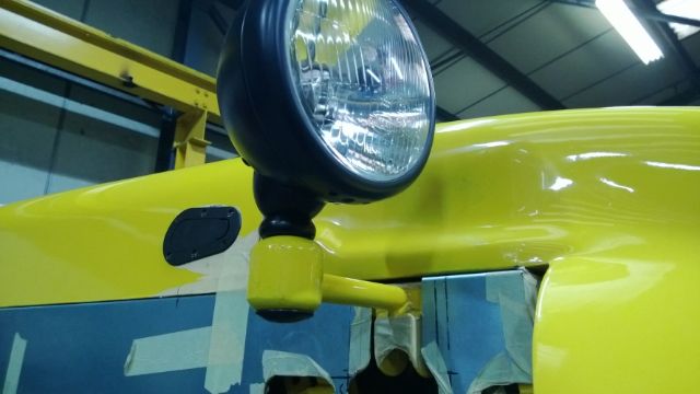
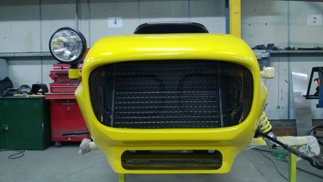
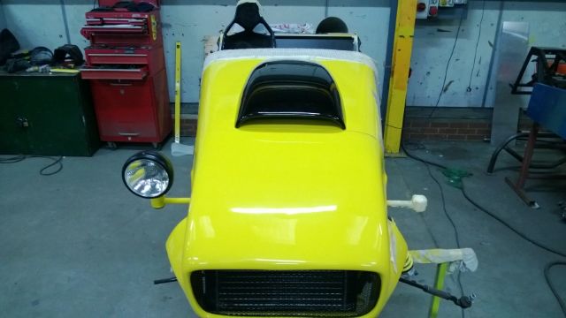
Just about finished the electrics up front with a couple of exceptions. So I thought I would have a break from all that electrickery and do some fabrication and bolt parts on. Pressed up my front grilles and bonded them in place this weekend. 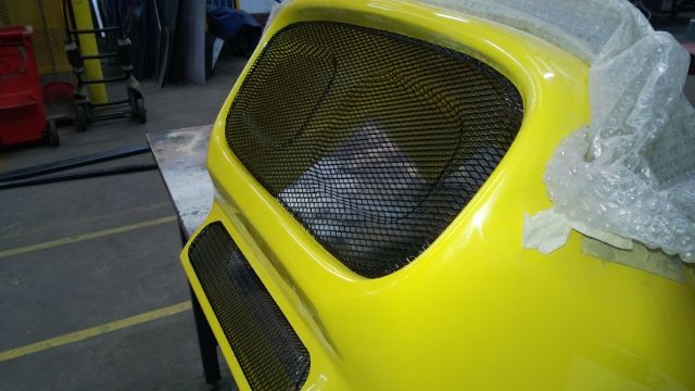 Used "TigerSeal" to bond the grilles to the GRP and don't think they will be going anywhere soon... My Christmas present finally arrived....LOL A Dax Rush bonnet scoop and I must say the finish is superb. 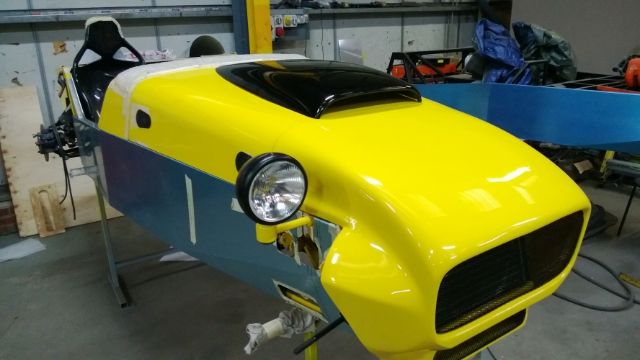 Was a bit concerned when I found out the scoop was the exact same length as my bonnet.......LOL |
Well computer or something is playing up so no descriptions just a few photos...
    |
Quote:
Still a bit worried about the bonnet not fitting? May use a scoop to hide and necessary hole! David |
Quote:
Have you had a look at Aerodynamix products. http://www.aerodynamix.co.uk/grp-and...roscreens.html Looks like some good products on there....:cool: On my car the bonnet only just touches the front leading edge of the cam cover. So now I have my scoop will be cutting a hole in the bonnet soon to clear the engine which should be pretty straight forward.... I hope...:eek: |
I've been thinking about making new rear top wishbones as I'm still not happy with the ones I currently have...
I've came up with two options.. Option 1. Inboard Rose Joints with the shock mount inline with the upright, which I think would put less load on the Rose joints. 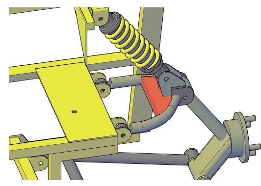 Option 2. Rose joints outboard mounted directly to the top of the upright with inboard poly bushes. The shock mount will not be inline with the upright as option 1.The Rose joints will be 12mm reduced down to 10mm to suit MX5 upright. I'm guessing this will put a lot more load on the joints but will it be too much or Ok? 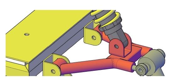 I'm using the Ultra strength 12mmx1.25 fine thread joints from McGill Motorsports. Any input good or bad will be most helpful. |
Well I've been researching a bit on the net and think I'll be going with option 1. :)
This should keep the loading on the Rose joints to a minimum. I guess only time and miles will tell...:eek: |
hazard switch
Johno,
when you wired in the hazard switch did you find it only had 2 wires for the switch and 2 for ilumination. I was planning on using the original mx5 switch and somehow removing the pop up headlight button that is on the same unit. When my mate came around last night he decided to look inside and now i have massive pile of various springs and connectors!! i am now going to wire in a new switch but all the switches i've seen seem to have about 7 terminals If you know the colours that would be fantastic (although judging by my loom they could easily be a different colour) David |
Quote:
If I remember correctly there should be an orange wire from the relay which is earthed through the switch... Hope that helps.:) |
Yes that makes sense.
Thanks David |
Quote:
One of the best ways though, would be to have an alignment bolt system, like Mazda fitted as OE to the MX-5. |
Quote:
|
Johno,
Why don't you design an in-board suspension system, where the shockers are hidden away in the bodywork ? I know space is limited, but by Christ, you would have some thing that looks really sweet. The only haynes with in board suspension. I would love to do it, but I have not got the expertise to see the plan through. Another idea I have, is to run the brake lines and wiring inside the wishbones. They are hollow, so why not ? Of course you have to think about strength, but you can't build a kick ass car without taking a few brave decisions. I am doing the wishbone idea myself. |
Quote:
And you would be silly to run fluid lines through hidden components. You have no way of seeing if there is an issue with the lines e.g. corrosion. You could have a real problem with the brake lines chafing with suspension travel, they wouldn't be adequately supported running though the wishbone. Plus, the most you'd be able to hide away is about 6" of line - hardly worth the effort IMO. It may also be against C&R/IVA. |
Oh bugger. Scrap the wishbone idea. Suppose there is only ever so much you can do with a 7. Gutted about the inboard suspension, that's what you get for trying to be clever !:rolleyes:
|
Hi all,
Skov's right, no more ideas please I'm now on Mk5 I think.....:eek: Well I'm glad you agree with option 1 Dave because their nearly finished...lol. The only thing I'm not sure about is do they need a support between the tubes where they weld to the upright bracket/shock absorber mount if you see what I mean. On my CAD drawing I have a piece of box between them but I'm not sure if it's needed? Hi Jason at some point I did think about inboard suspension but I don't know enough about it....:o Yeah would be nice having the pipes down the tube would it be OK for the IVA? So what setup you thinking of making? |
Quote:
The inboard suspension is a nice idea and it can work; it's been done plenty of times before. It is extra design and fab work, the question is would you gain enough to make it worthwhile? As far as I know, 3GE built that 1 chassis and no more. I don't know why, there has to be a reason (and I'm not saying because it didn't work, I genuinely do not know why they didn't pursue it further). |
Quote:
(IMO) long answer - I suppose it would depend on the design of the upright and the length of the wishbone as well as the damper length you're running (and probably more besides) as you would need to determine the position of the lower damper mounting relative to the upright upper mounting. That area is going to have high load through it. If you are still near the SSC/NTS design in terms of geometry, or if it's similar to your CAD image, I would say it would be worth putting a support plate in, as per the original SSC/NTS design. |
Well I've finished my latest design of rear wishbone, Mk5 I believe...:o
That's it, no more changes or tweaks its done... Hi Dave, I kept to the CAD drawing and fitted a piece of 25mm SHS between the tubes and fully welded it to the upright bracket support. The design keeps the shock length the same as the Saturn spec which is convenient as I purchased some shocks this week to that specification. 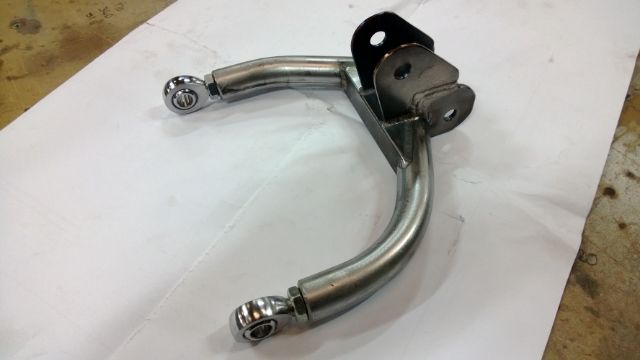 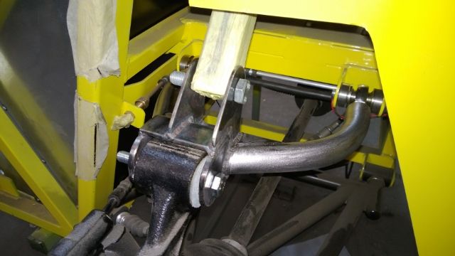 I feel a lot happier now with this design as it's a lot stronger than the one I had on the car and is still adjustable. I've upgraded the tube size from 19mm to 25mm to accommodate the weld in Rose joint threaded adapters. So these are now ready for powder coating. I also got round to bonding my big head fasteners to my bonnet scoop today ready for drilling my bonnet tomorrow and test fitting... Sorry no photo yet. Still haven't plucked up the courage yet to start the engine...:eek: I was planning to have my exhaust by now ready for the first turn but not quite gone to plan.....LOL |
| All times are GMT +1. The time now is 03:57 PM. |
Powered by vBulletin® Version 3.6.4
Copyright ©2000 - 2025, Jelsoft Enterprises Ltd.