NTS MX5 Build
Hi Nathan,
Any chance of a few piccy's of your progress for the MX5 build codenamed "Bumble Bee" or will you be keeping it under wraps untill it's finished?:) ps... How's Spud doing, haven't seen any posts lately from him.. Johno |
Iv just got the cage to finish and interior panels before the final fitment of the bodywork and finishing off, i was hoping to get it lokking pretty before i put some photos up but il put some up on photobucket tonight for ya,
ps johno can you pm me the address to send the crush tubes, lost it lol |
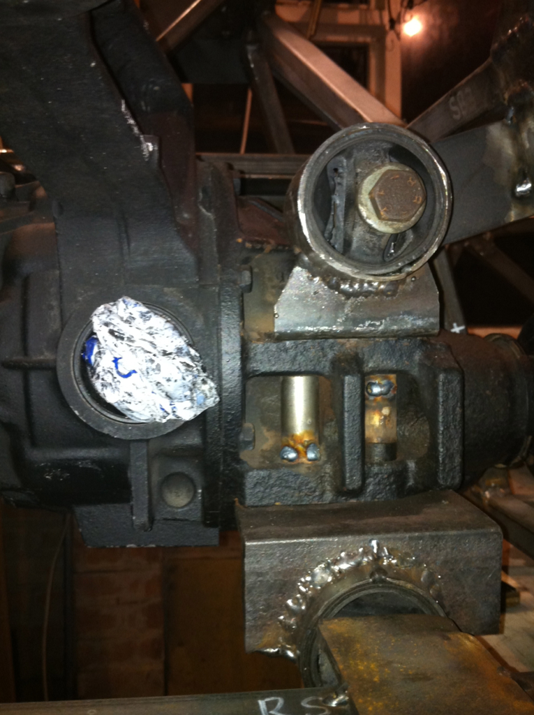
Sorry for the delay, iv been trying to catch up this week. Its been a bit bitter sweet the last couple of weeks regarding the mx5 build. A couple of weekends ago id sorted out the wiring loom and got all the fluids bled so i decided it was time for a proper run down round the industrial estate to find any proplems before i started putting the bodywork on. So, as one does I spent a good hour and a half checking bolts, tiying back any loose wiring/tubing etc. I popped the battery in the passenger footwell, turned the key and started driving slowly around the industrial estate in first and second. I went back to the unit and gave it a once over, everything looked dandy so i decided to give it the beans down the road. Going from first to second at speed there was an almighty bang, and i was hit by something hard from behind. The prop was laid on the floor and the diff was snapped in two. Like a complete knob i had forgotten to put the spreader plates under the diff bushes so the diff was hanging by just its rubbers. The torque was too much for it and it gave way, snapping the rear casing in half and wrecking the UJ in the prop in the process. I pushed it back for what what seemed to be a lifetime, with an almighty bruise on my arse from the diff twating me!
The good news was that there was no damage at all to the chasiss, so theres no problems there. David bowlam was very kind to let me have a replacement, but as it was a 1.6 diff it has different pcd shaft flanges and it was open, i really wanted to keep the torson lsd so a quick call to mx5 city got me a free new casing (providing i show their stickers on the car in the mag features!) The diff is now back in the car with its new casing. I have also fitted a pair of these: http://www.ebay.co.uk/itm/Mazda-MX-5...item3f125b3c0a and made some 8mm spreader plates to go underneath. So, whatever you do, dont hang the diff without the original plate with the castlated bush or polybushes and a substansial spreader or this will happen! 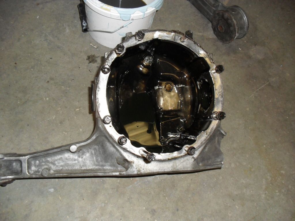 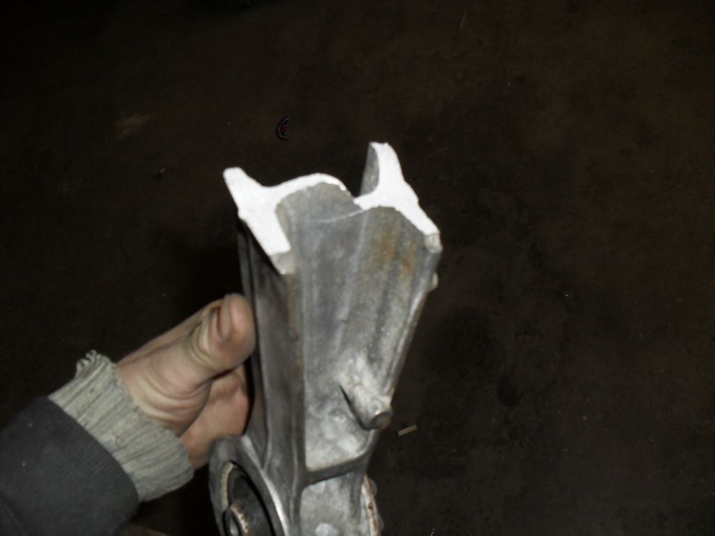 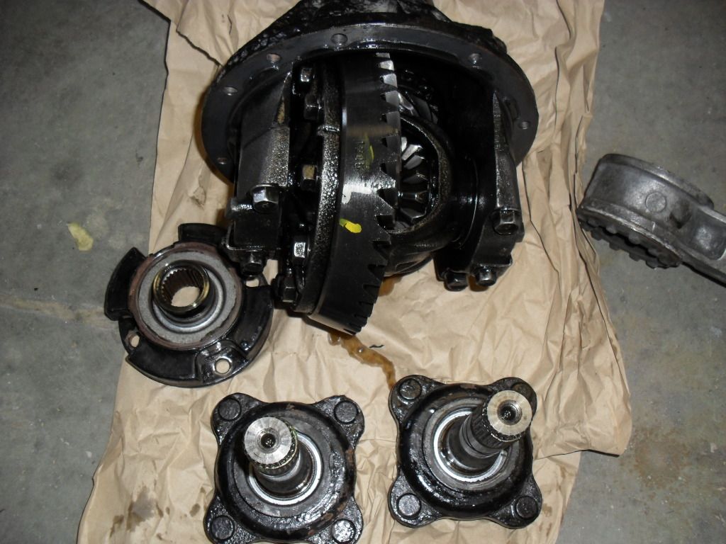 I cant thank mx5 city enough, there a real good bunch of blokes who really know their mx5s, and they'll sell you anything from a nut to a full donor! |
Anyway the diffs back in place now, im just finishing tidying up the wiring and hoses, then its onto the interior panels and rollcage followed by the bodywork which is all trimmed ready for fitting. I just cant seem to find the time at the moment, but theres a trackday looming on the 10th of april and im determined to make it. I may have to piss the missus off and put in some overnighters!
couple of sneaky pics from the old brick... 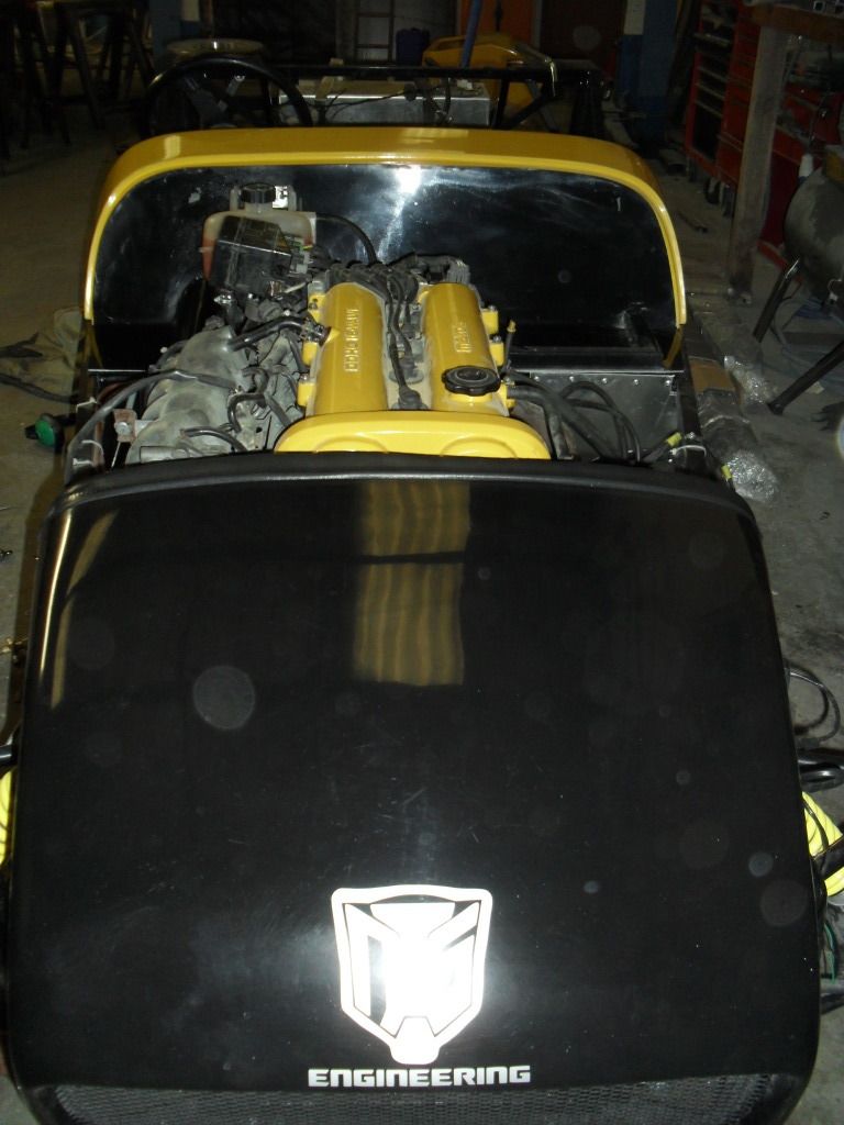 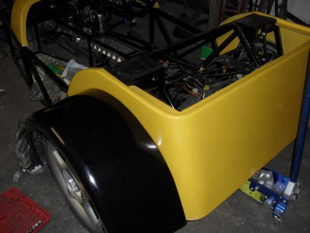 made up some sexy looking headlight brackets for the 5 inchers tonight... 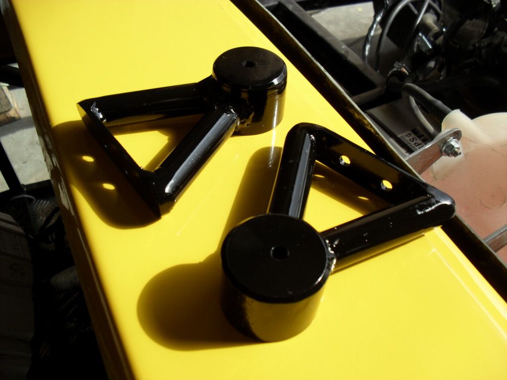 |
Glad I'm using 1.6mm steel for the seat back.:cool: Just in case!! Looks great. good to see it moving along.
|
Love the light bracket.
|
Toblerones needed methinks as in triangles
|
Hi Nathan,
I bet that was a scary moment...:eek: When we bolted our diff in we decided to use the diff washers mounted to a bracket welded to the underside of the diff plate. 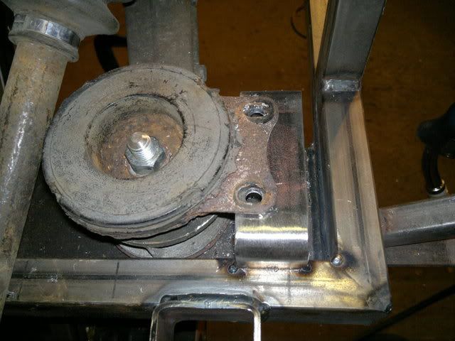 The problem is my diff washers are badly corroded and I am looking to buy some second hand ones as I can't source new ones (unless somebody knows where). The question I now ask is are these the only areas to look at? On the MX5 they have a substantial frame bolting the diff to the gearbox, I personally am now looking at my diffs rubber mount as well and will probably beef this up. Also I am going to insert a pressed plate between the two diff mounts taking out any twist between the two mounting points. 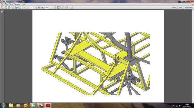 Probably overkill I know but looking at your photo makes me shudder... You said you had no other damage to your chassis so was the diff rubber mount ok? You also mention a spreader plate but not sure what you mean by this, so any photos or diagrams would help. Sorry to hear about the setback ...Johno |
Triangulation is stronger and a better bet than just adding even more heavy gauge plate because heavy cars hit things harder......light 'n triangulated is the way to go
|
Take a look at the rear of any of the cars Jeremy Philips has designed and you will see much goodness and a distinct lack of girders.:cool:
|
Did you not have the diff side bolts fitted? (where the power plant frame bolts up)
|
Is it just me or does looking at the photo of the point of failure and actually reading Nathan's description of what happened / how he mounted it, make it clear this had nothing to do with a need for extra triangulation, 'girders' or any modification to the diff cage at all!!! The thing snapped a diff IN HALF before having a chassis failure!!!
What actually happened in this case, if you fit a winged diff just by running a bolt through the crush tube directly the mounting point the load is completely suspended by the rubber bush with no limit in travel... Put a large turning force through it, one wing is pressed hard up against the chassis while the other is pulled down hard pulling / flexing the bush as far as the rubber part will stretch... This can only go so far before something goes crunch! If you mount the diff with no caps on the bushes, even on the original MX5 subframe and and drive it hard will pull itself to pieces... The fact it wripped a diff in half and didn't budge the diff cage plates proves Andrews design is sound... Just make sure you fit the thing correctly with no missing parts |
Quote:
|
Quote:
The rear casting on the mx5 diff is actually pretty poor in terms of stregnth, it weighs less than 1 kilo and when inspected, there are large air bubbles within the alloy, you could drop one from less than a meter and shatter it to bits. The only ones that are stronger are the smooth cased castings used on some of the early viscous diffs which are crap in comparison to the torsens, they are rare as rocking horse shit though, iv heard of the drift boys paying £250 just for a case to fit to locked torsens |
Quote:
BV. |
Yes as per chassis design
|
Quote:
The diff to power plant frame is the main fixing for the diff. BV |
If you look at the mnr chassis this is mounted in a similar way to the nts/saturn version and it seems to work for them. I am sure that once the plates are on both sides of the rubber mount this won't happen again. Here is a picture of the mnr version. The westfield version also seems very similar. Both of these only seem to use the front mounts ( in the steel section) to stop this rotating forward and backwards.
http://www.google.co.uk/imgres?q=mnr...QWG9cAK&zoom=1 |
The MNR works because it's a mass of triangulated tubes not open rectangles/squares, that and Marc Norden knows how to grow onions:D
|
Sorry @MarkB , I don't see the logic in your posts at all... Are you saying this diff failure wouldn't have happened if the diff cage / chassis was further reinforced? Not trying to be offensive, I'm just not sure what you're trying to get at!
Can understand the need for more rigid mounting on the nose of diff but the overall cage / rear frame design and support of the diff wing has nothing to do with this failure. The tortional forces on the wing bushes are nothing compared to those on the nose mounts. Use the correct bush caps, mount the nose properly and diff won't dismember itself. A more contructive input would be telling everybody where you think this additional triangulation needs to go (?) |
Quote:
Rather than guess at the problem or assume someone else has solved the problem on their design. (westfield still have problems with their solidly mounted arangement.) lets try to understand the problem and then solve it! Firstly the failure mode needs to be understood. Currently no one other than Jenks seems to have correctly identified what actually happened to cause the failure and so we make no progress in resolving the problem we just create a pile of broken diff carriers! To understand what has happened we first need to understand how the power plant assembly in the donor vehicle works. The engine and gearbox are rigidly bolted together and the powerplant frame is tightly fitted to the gearbox and the diff. This creates a complete unit which is mounted to the front subframe by two mounts on the engine which primarily are to control the engines verticle movement over bumps and reduce vibration transmitted to the passenger cabin and two rubber isolators on the diff carrier which are to isolate vibration. They provide some small resistance to rocking side to side motion but cars with a power plant assembly such as the MX5 have very little side to side movement under even the hardest accels due to the powerplant all being connected together and the torque forces largely canceling each other out. The torque reaction to the driven wheels is resisted as the diff cannot lift the engine/gearbox assembly attached at the other end of the powerplant frame and thus the diff is constrained totally in movement in this direction. In mounting the diff in isolation the nose of the diff needs to be tightly constrained and herein lays the cause of the failure. The ex engine mount is being used in tension for which it was not designed and can therefore not sufficiently prevent the diff nose from moving vertically upward under drive as the diff reacts to the torque appplied at the rear wheels. The two mounts on the diff carrier were never designed to work in this way and the diecast ally case fails exactly as described. This problem has a well trodden path and the solution lays in controling the diff nose. Triumph had the same problem in the 1950's when designing the triumph herald/spitfire and they resolved it by bolting a bracket to the diff nose and stiff mounts to the chassis and I would suggest a similar arangement with some sort of laser cut bracket that can fix to the mazda PPF mounting and via suitable mounts to the chassis. Hope this has helped people to understand the problem and enable all to work toward a solution. BV:) |
Quote:
It's obvious where the rear cradle is weak as it is open rectangles with no triangulation and the diff is fixed to this........less is more usually and take a good look at how Marc Norden has done the MNR, simple yet very effective. |
Quote:
It is how the diff is mounted to the chassis not chassis flex itself that has caused the problem. The diff has moved because its not fixed to the chassis in a way that constrains the movement of the diff nose. Quite simply the diff nose mounting rubber has too much movement in it. The nose of the diff rises as a reaction to the road wheels driving forward, the twist on the alluminium diff carrier exceeds the strength of the carrier and it fails exactly as in the pictures NTS posted. What is needed is a better diff nose mounting arangement to constrain the movement. As said previously, Mazda designed the diff mounts for vibration isolation rather than to constrain torque reaction. I like the way MNR have mounted the two rear mounts but they do still have diff problems - just view the locost usa site and have a look. BV:) |
I would tend to agree with BV ....I have seen the diff cage in question and there is NO evidence of any weakness/distorsion whatsoever ...if fact there was barely a scratch which is testament to a good design rather than poor
|
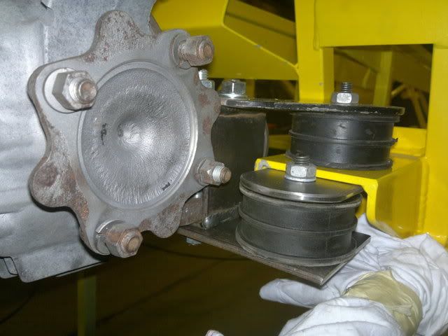
I've used two volvo engine mounts top and bottom orientated so that the top one is resisting vetical movement and the bottom one horitantal movement. So I'm covering any rotational movement. It looks nasty in this image as I haven't finished bracing the chassis brackets and tidying them up.
 Not a great picture. I'll try and get a better one in good lighting. |
Quote:
|
Quote:
I have seen no evidence to suggest the chassis doesn't take the forces placed upon it which arn't great in the donor vehicle anyway. The two mounts for the diff carrier are just as they are in the vehicle I looked again at the ones in my MX5 at lunchtime. Whilst I suspect the NTS/Saturn front bracket would crack adjacent to the weld that was not the point of failure in this case. It was the rubber ex-engine mount not being the correct type to restrain the diff nose verticle movement that has caused the failure and judging by some posts on locost usa some MNR builders are having similar problems. Two or three bloggers I looked at last night are experimenting with different stiffnesses of mount to try and overcome diff carrier cracking so I'm by no means convinced MNR have it right either, and I know the westfield miata has had problems. CTWV50 has the right idea but I seriously doubt engine mounting rubbers will be sufficiently stiff to control the diff voided bushes will still have too much movement. Something along the lines of a poly bush at around shore 90 acting as CTWV50 has his will control the diff leaving the two isolators in the diff carrier largely to do what they do in the donor car which is to soak up vibration. Indeed it may make more sense to ingore the two mounts on the diff carrier altogether and go for robust mounting of the diff via the PPF mounting system. Has anyone considered using the back part of the PPF and mounting that to the chassis I wonder. BV:) |
Hmm, thanks for the costructive critisism, I'm only running a cheap 1.6 open diff atm so if it does fail with this design I'll upgrade to a torsen and rethink the design. I think most people will of thought about a solid mounting to the chassis but surely you would end up with alot of vibration through the chassis which would cause other reliability issues.:)
edit: Have you got any links BV for the failures on locostusa? What's your source for the westield miata issues? Cheers Chris |
 May be of some help in visualising things... |
Quote:
Steve |
Quote:
|
Quote:
As said already your design shows you have been thinking about how to mount the mazda diff and the unusual problems its design has created. Heavy duty engine mounts perhaps rally spec would get the job done. I came across the problems with westfield miata when I strumbled across the build thread for the car flyin' miata built. The others including the locostusa came yesterday when I did a google search for MX5 miata diff mount problems. Sorry I didn't do any links to these sites I was just havin' a beer and surfin':D Well done TQ uk - I like the gold brace on your RX8/Current MX5 rear end. That would be a good way of dealing with the problem, maybe just use the rear 6-8inches of the power plant frame or a lazer cut and folded substitute. That brace would constrain the diff nose and assist the two mounts in the diff carrier. BV:) |
I think Big Vern and CTWV50 pretty much have it sussed... Mr Gibbs designed the framework of the seat back to soak up the torsional loads of the diff, so that's where we need to send them in this design too. If we can do that and get some vibration isolation (poly bushes) then it's win-win, jelly and icecream for everyone!
Does anybody have a 3d cad file of the Saturn chassis with a model of the diff in place? (SolidWorks, Inventor or the like) I'm thinking of something along the lines of a bracket mounted at 90 degrees to the right-hand seatback upright then a mount along the lines of Skov's diff nose mount but with 2 polly mounts fixed a 90 degrees, spaced a good distance apart to spread the loads acting under tension and compression... Skov's design looks really nicely engineered but the mounts will be under shear forces when they're designed for compression (and I think they're rubber) http://1.bp.blogspot.com/-rANr4WQ7IX...unt_fitted.jpg http://3.bp.blogspot.com/-MVpVJo0hIs...t_fitted_2.jpg |
Well had a play about with the diff mounting today and managed to fit a welded frame to the nose of the diff and two rubber mounts.
 Bit of a tight fit but it all goes in....just.....:) Also fitted the spreader plate to one side of my diff bolted to my chassis bracket. 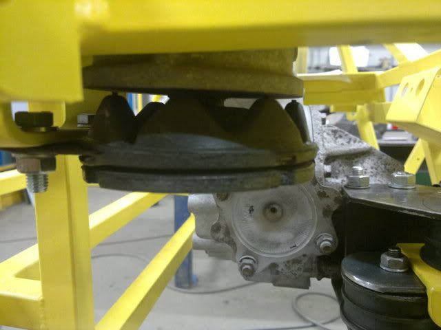 Obviously the spreader plate is in line with the bush and the spreader is at an angle to the diff housing. Does anybody know if this is the case on the MX5 or is the chassis mounting at an angle to run in line with the diff housing. Johno |
Well I guess it's pretty much covered by BV and Jenks.
I guess the difference between the Sierra diff and MX5 is the Sierra doesn't have arms sticking out both sides making any torque movement worse. Sodily mounting the front nose of the diff will only cause metal fatigue and fracture of the chassis sometime in the future. Mazda realised this and fitted a PPF as standard. Triangulation of the chassis will only make things worse resulting in a weld faiure along the HAZ of a weld. I spoke to Nathan Sunday and the only reason the diff broke was because he forgot to fit the diff washers....LOL.. Ok he agrees the diff mounting below the diff wasn't upto the job but this didn't brake. Basically if the front nose of the diff was to be solidy mounted as per Westfieid and others who grow onions then Mazda could have saved a lot of RD money. Well just my thoughts I guess others will disagree........:D But I look at it this way, if Mazda fitted it it's good enough for me... Johno |
You do realise that IVA inspectors monitor forums like this :D
|
MarkB please get a life!
|
Quote:
|
What you're doing on this forum is nothing new to most people, it's quite clear you enjoy trolling this forum for your own reasons. I guess the best thing people can do is just ignore your posts as they really serve no useful purpose.
You may enjoy this little youtube video. http://www.youtube.com/watch?v=HaMOcJfsksI For anyone who doesn't know what Mr. MarkB and his aliases is up to.... http://en.wikipedia.org/wiki/Troll_(Internet) |
Quote:
|
| All times are GMT +1. The time now is 08:18 PM. |
Powered by vBulletin® Version 3.6.4
Copyright ©2000 - 2025, Jelsoft Enterprises Ltd.