
|
|
#231
 11th June 2013, 07:00 PM
|
|||
|
|||
|
Yes that makes sense.
Thanks David
__________________
Click to see my build photos on Flikr http://www.flickr.com/photos/67112582@N03/ Saturn MX5 Based Chassis, Limited Slip Diff & 2.4 Quick Rack. Build cost.... seems to be spending more on tools than car bits at the moment! (they will be handy in the future though). Car iva'd and passed 15/08/2014. Finished weight 572kg. 
|
|
#232
13th June 2013, 06:43 PM
|
|||
|
|||
|
Quote:
One of the best ways though, would be to have an alignment bolt system, like Mazda fitted as OE to the MX-5. Last edited by PorkChop : 13th June 2013 at 08:47 PM.
|
|
#233
13th June 2013, 06:47 PM
|
||||
|
||||
|
Quote:

|
|
#234
13th June 2013, 08:06 PM
|
|||
|
|||
|
Johno,
Why don't you design an in-board suspension system, where the shockers are hidden away in the bodywork ? I know space is limited, but by Christ, you would have some thing that looks really sweet. The only haynes with in board suspension. I would love to do it, but I have not got the expertise to see the plan through. Another idea I have, is to run the brake lines and wiring inside the wishbones. They are hollow, so why not ? Of course you have to think about strength, but you can't build a kick ass car without taking a few brave decisions. I am doing the wishbone idea myself.
|
|
#235
13th June 2013, 08:28 PM
|
|||
|
|||
|
Quote:
).And you would be silly to run fluid lines through hidden components. You have no way of seeing if there is an issue with the lines e.g. corrosion. You could have a real problem with the brake lines chafing with suspension travel, they wouldn't be adequately supported running though the wishbone. Plus, the most you'd be able to hide away is about 6" of line - hardly worth the effort IMO. It may also be against C&R/IVA.
|
|
#237
13th June 2013, 08:43 PM
|
||||
|
||||
|
Hi all,
Skov's right, no more ideas please I'm now on Mk5 I think.....  Well I'm glad you agree with option 1 Dave because their nearly finished...lol. The only thing I'm not sure about is do they need a support between the tubes where they weld to the upright bracket/shock absorber mount if you see what I mean. On my CAD drawing I have a piece of box between them but I'm not sure if it's needed? Hi Jason at some point I did think about inboard suspension but I don't know enough about it....  Yeah would be nice having the pipes down the tube would it be OK for the IVA? So what setup you thinking of making?
__________________
Any intelligent fool can make things bigger and more complex... It takes a touch of genius - and a lot of courage to move in the opposite direction. Albert Einstein http://s1199.photobucket.com/albums/aa472/JohnoSS1/ Johno
|
|
#238
13th June 2013, 08:46 PM
|
|||
|
|||
|
Quote:
The inboard suspension is a nice idea and it can work; it's been done plenty of times before. It is extra design and fab work, the question is would you gain enough to make it worthwhile? As far as I know, 3GE built that 1 chassis and no more. I don't know why, there has to be a reason (and I'm not saying because it didn't work, I genuinely do not know why they didn't pursue it further).
|
|
#239
13th June 2013, 09:12 PM
|
|||
|
|||
|
Quote:
(IMO) long answer - I suppose it would depend on the design of the upright and the length of the wishbone as well as the damper length you're running (and probably more besides) as you would need to determine the position of the lower damper mounting relative to the upright upper mounting. That area is going to have high load through it. If you are still near the SSC/NTS design in terms of geometry, or if it's similar to your CAD image, I would say it would be worth putting a support plate in, as per the original SSC/NTS design. Last edited by PorkChop : 13th June 2013 at 09:18 PM.
|
|
#240
15th June 2013, 06:50 PM
|
||||
|
||||
|
Well I've finished my latest design of rear wishbone, Mk5 I believe...
That's it, no more changes or tweaks its done... Hi Dave, I kept to the CAD drawing and fitted a piece of 25mm SHS between the tubes and fully welded it to the upright bracket support. The design keeps the shock length the same as the Saturn spec which is convenient as I purchased some shocks this week to that specification. 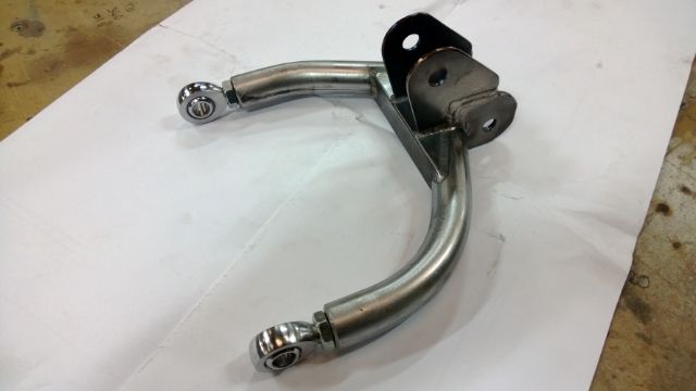 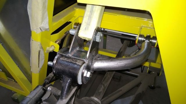 I feel a lot happier now with this design as it's a lot stronger than the one I had on the car and is still adjustable. I've upgraded the tube size from 19mm to 25mm to accommodate the weld in Rose joint threaded adapters. So these are now ready for powder coating. I also got round to bonding my big head fasteners to my bonnet scoop today ready for drilling my bonnet tomorrow and test fitting... Sorry no photo yet. Still haven't plucked up the courage yet to start the engine... I was planning to have my exhaust by now ready for the first turn but not quite gone to plan.....LOL
__________________
Any intelligent fool can make things bigger and more complex... It takes a touch of genius - and a lot of courage to move in the opposite direction. Albert Einstein http://s1199.photobucket.com/albums/aa472/JohnoSS1/ Johno
|
 |
| Thread Tools | |
| Display Modes | |
|
|


")


 Linear Mode

