Haynes Forums  

Go Back   Haynes Forums > Haynes Roadster Forums > Donor cars
FAQ Members List Calendar Search Today's Posts Mark Forums Read

Reply
 
Thread Tools Display Modes
  #11  
Old 22nd May 2009, 01:19 AM
rmccomiskie rmccomiskie is offline
Junior Member
 
Join Date: Apr 2009
Posts: 9
Default

Quote:
Originally Posted by Danny View Post
Theres quite a few people worldwide who are interested in using BMW parts some specific drawings and measurements (perhaps as an ANNEX to the book) and stickied on the forum might be good.


.......please
Here in the U.S., there's plenty of 3 Series BMWs in the wrecking yards. It's one of the few RWD cars left. I'm leaning toward the 1992-95 318i (E36 w/M42 engine) for the engine, trans, diff, front uprights, F/R brakes, maybe steering column. The rear hub carriers don't look usable so those may need to be fabricated. The diff mounting looks similar to the Mazda Miata IRS so that's been done before on Locost chassis.

Longerr has already proved that the engine & trans can be used: http://picasaweb.google.com/Longerr82/Project7#

I agree that we need to gather some measurements to see what alterations are needed.

Bob.
Reply With Quote
  #12  
Old 22nd May 2009, 08:32 AM
Danny Danny is offline
Junior Member
 
Join Date: May 2009
Location: Palmerston North, NZ
Posts: 8
Default

My main motivation for this is because here in NZ (I am unsure what it is like everywhere else in the world) the popularity of drifting has made any RWD Performance japanese car parts hideously expensive, forget getting a sierra over here so that pretty much leave BMW as they are one of the few makers whose majority of cars (even the lower spec'd and therefore cheaper ones) are RWD.

Another question (though it may be stupid) would the BMW 6 Cylinders fit into a 7?

Last edited by Danny : 22nd May 2009 at 12:05 PM.
Reply With Quote
  #13  
Old 22nd May 2009, 02:48 PM
Chris Gibbs
 
Posts: n/a
Default

The fabricated front upright bolts to the same mountings as the original strut, which has a much longer moment arm. There shouldn't be any strength problems.

Designing the upright presents an almost unique opportunity to specify the ideal geometry for the application (well unique to us mortals - Ford always do it )

The designer can specify caster, camber, king pin inclination and scrub radius, not something that you can do with a "donor" upright. Usually you need to start by working around the chosen upright's limitations!

I'd like to do the designing myself now but I'm just too busy at the moment, soon though

Cheers

Chris
Reply With Quote
  #14  
Old 22nd May 2009, 05:57 PM
rmccomiskie rmccomiskie is offline
Junior Member
 
Join Date: Apr 2009
Posts: 9
Default

Quote:
Originally Posted by Chris Gibbs View Post
...Designing the upright presents an almost unique opportunity to specify the ideal geometry for the application (well unique to us mortals - Ford always do it )

The designer can specify caster, camber, king pin inclination and scrub radius, not something that you can do with a "donor" upright. Usually you need to start by working around the chosen upright's limitations!

I'd like to do the designing myself now but I'm just too busy at the moment, soon though
Thanks for volunteering Chris. Of the 2 drawings you previously posted, one shows the fabricated part straddling the upper mounting ear and the other shows it bolted to the side of the ear. Even though it might mean the fabricated upper ball joint attachment has to be angled somewhat for proper geometry, it seems to me that the straddled approach would be less likely to flex the mounting bolt.

In your design, perhaps you can consider instructions that accomodate different KPI, caster, scrub radius, wheel offset, tire size. Something like a simple geometric drawing that shows where the upper ball joint has to be given all the parameters. Just my 2 cents.

Waits eagerly...
Reply With Quote
  #15  
Old 22nd May 2009, 06:30 PM
rmccomiskie rmccomiskie is offline
Junior Member
 
Join Date: Apr 2009
Posts: 9
Default

I've found a few pics of BMW E30 and E36 differentials for comparison. I believe both chassis were fitted with small (318) and large (325) diffs.

E36 front mount is a single bolt on the lower right side inserted horizontally front to back.


E36 rear mount is a two eared affair integrated into the rear cover. This is a small case judging by the single top bolt in the rear cover. Large cases have 2 bolts.


E30 front mount is four bolts inserted vertically.


E30 rear mount is a single ear on the left side integral with the rear cover. This pic is the small case. Note the single top bolt in the rear cover.

Reply With Quote
  #16  
Old 22nd May 2009, 10:03 PM
Danny Danny is offline
Junior Member
 
Join Date: May 2009
Location: Palmerston North, NZ
Posts: 8
Default

So that adaptor for the front hub is only to extend the height to the upper A arm? Are there other uprights that can be used as like i mentioned before sierra's are pretty hard to find over here.

Another awesome thing to see would be this
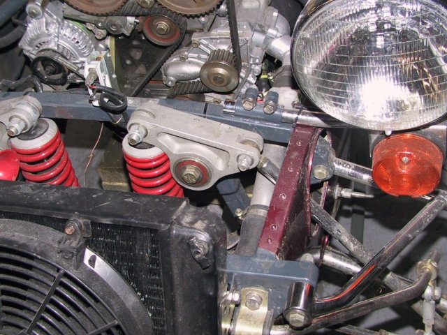


An inboard upright setup, this is the one used by fraser cars in NZ so I am not sure if there are patent issues or anything.
Reply With Quote
  #17  
Old 22nd May 2009, 10:07 PM
Danny Danny is offline
Junior Member
 
Join Date: May 2009
Location: Palmerston North, NZ
Posts: 8
Default

Quote:
Originally Posted by rmccomiskie View Post

Longerr has already proved that the engine & trans can be used: http://picasaweb.google.com/Longerr82/Project7#

Bob.
On that one it looks like they have got around the problem by mounting the upper A arm lower down the Chassis. (or is this where it is supposed to be?)
Reply With Quote
  #18  
Old 22nd May 2009, 11:16 PM
Chris Gibbs
 
Posts: n/a
Default

Quote:
Originally Posted by rmccomiskie View Post
Thanks for volunteering Chris. Of the 2 drawings you previously posted, one shows the fabricated part straddling the upper mounting ear and the other shows it bolted to the side of the ear. Even though it might mean the fabricated upper ball joint attachment has to be angled somewhat for proper geometry, it seems to me that the straddled approach would be less likely to flex the mounting bolt.

In your design, perhaps you can consider instructions that accomodate different KPI, caster, scrub radius, wheel offset, tire size. Something like a simple geometric drawing that shows where the upper ball joint has to be given all the parameters. Just my 2 cents.

Waits eagerly...
The two versions of the fabrication exist because I haven't done any work on the geometry.

I'd better explain that, One of the set ups will be better for caster, but I don't know which. Obviously the version with the upright stradling the strut mount would be prefered (double shear) but it might be that the geometry requires the offset version, for example if the balljoint articulation is beyond limits.

As I said in my previous post it's an oportunity to decide your own parameters, suspension design is facinating but always a compromise with opposing factors and I think it would be beyond the scope of a build your own type book to do justice to the subject. I'd recommend "competition Car Suspension" by Allan Staniforth (RIP) if you want to get into it.

The design would be my best compromise taking into account weight, wheel rates, required roll centres, etc with adjustability built in for people to tinker.

Camber adjustment is easy to accomodate if the design uses the Transit drag link end, caster can be adjusted by spacing the bottom and top wishbones (not a lot I'll grant you) KPI is really a function of design, and needs to be set when the upright is made, although camber changes will alter the angle slightly, and scub radius can only be altered, when KPI has been set, by varing wheel offset.

It's worth noting that lowering the top wishbones will extend the roll centres almost to infinity, efectively making the set up into a swing axle - think VW Beetle - it'll keep the chassis off the floor but it was abandoned for performance cars in the 1930's!

Cheers

Chris
Reply With Quote
  #19  
Old 23rd May 2009, 12:01 AM
Danny Danny is offline
Junior Member
 
Join Date: May 2009
Location: Palmerston North, NZ
Posts: 8
Default

please keep working on it, im looking foward to what you come up with.
Reply With Quote
  #20  
Old 24th May 2009, 06:00 PM
Chris_ Chris_ is offline
Member
 
Join Date: May 2009
Location: Clacton, Essex, UK
Posts: 34
Default

Quote:
Originally Posted by rmccomiskie View Post
Looking at the E36 front uprights, BMW didn't mind bolting a 'doodah' to it. The strut is attached to the back of the upright with 3 bolts. That strut has a lot more leverage than the top wishbone would have. It seems to me that a properly designed 'doodah', one that provides the desired geometry, would be quite strong and perfectly safe.

Bob.
I wasn't saying ot for the strength side of things, more, as you say, the geometry side of things.

Not sure i'd fancy knocking one up with a bit of plate and a MIG, and certainly not two identicals

Chris

PS, E30 & E36 diffs are either small or medium case. The large case goes on the bigger models (5, 6, 7 series) oh and the rear cover is interchangable between e30 - e30 smalls and e30 - e36 mediums. (ie. not small to medium or vice versa)
Reply With Quote
Reply


Thread Tools
Display Modes

Posting Rules
You may not post new threads
You may not post replies
You may not post attachments
You may not edit your posts

vB code is On
Smilies are On
[IMG] code is On
HTML code is Off
Forum Jump


All times are GMT +1. The time now is 07:29 AM.


Powered by vBulletin® Version 3.6.4
Copyright ©2000 - 2024, Jelsoft Enterprises Ltd.