Haynes Forums  

Go Back   Haynes Forums > Haynes Roadster Forums > General discussion
FAQ Members List Calendar Search Today's Posts Mark Forums Read

Reply
 
Thread Tools Display Modes
  #61  
Old 31st December 2014, 01:57 PM
ayjay ayjay is offline
Senior Member
 
Join Date: Dec 2010
Location: Coedpoeth near Wrexham, North Wales
Posts: 737
Default

Whens the divorce ?
Reply With Quote
  #62  
Old 31st December 2014, 07:02 PM
Rosco Rosco is offline
Senior Member
 
Join Date: Sep 2014
Posts: 493
Default

Quote:
Originally Posted by ayjay View Post
Whens the divorce ?
Haha, not yet, she's putting up with it at the min
Reply With Quote
  #63  
Old 31st December 2014, 07:02 PM
Rosco Rosco is offline
Senior Member
 
Join Date: Sep 2014
Posts: 493
Default

Bit more done today, had my dad helping me today!

Got the engine slung up so it's picking it up somewhere near level of how it will sit in the car


Then decided to make a trolly for the rsj as the clamp I had didn't slide very wheel


Reply With Quote
  #64  
Old 31st December 2014, 07:03 PM
Rosco Rosco is offline
Senior Member
 
Join Date: Sep 2014
Posts: 493
Default


Then we made a trolly to sit the engine on, so we could drop the car over and move it around, then once happy with the position I get get the mounting cradle sorted without having to have it dangling in mid air

Reply With Quote
  #65  
Old 31st December 2014, 07:03 PM
Rosco Rosco is offline
Senior Member
 
Join Date: Sep 2014
Posts: 493
Default

I can rase the car up or down to alter the mounting height, I'm just waiting to hear back from AB performance on his zx10 sump height, I'm hoping to have the underside of the sump flush with the underside of the car

I need to decide on position next, from the pictures I've seen most seem to be mounted towards the rear of the engine bay

But some seem to be straight and some to be on an angle parallel with the side rail, on reading it looks like the output flange and the diff flange are supposed to be parallel, if anyone could help out that would be great
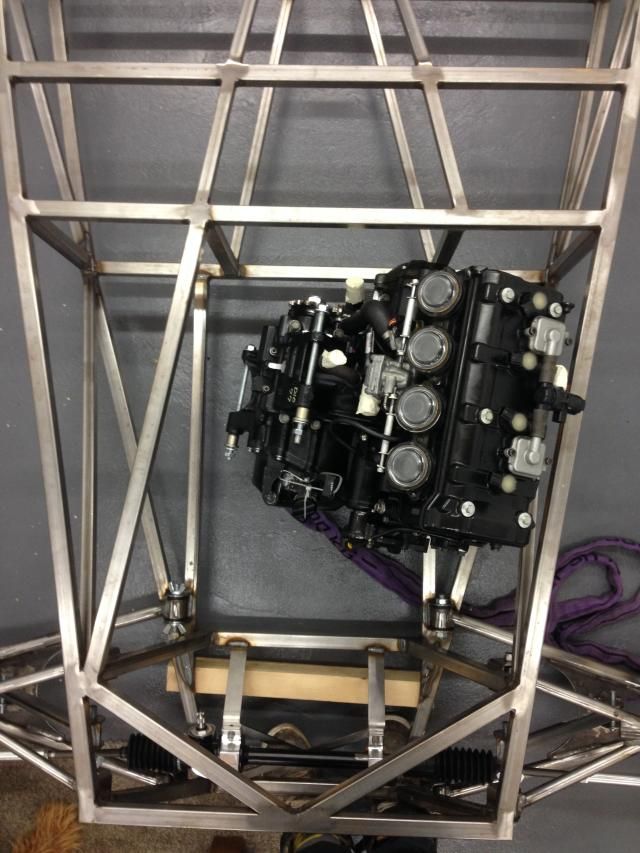


Thanks for looking
Reply With Quote
  #66  
Old 31st December 2014, 08:10 PM
wylliezx9r wylliezx9r is offline
Senior Member
 
Join Date: May 2010
Location: South Wales
Posts: 321
Default

When I had a bike engine in mine it was parallel with the Centre line of the car like your 2nd picture and everything worked as it should. If I remember correctly when the car was corner weighted it was 520 kg with a full tank so there's a benchmark for you.

I'm running S2000 power now though and I much prefer the nature of a car engine but horses for courses and all that
Reply With Quote
  #67  
Old 1st January 2015, 09:50 AM
Tatey's Avatar
Tatey Tatey is offline
Senior Member
 
Join Date: May 2009
Location: Leicester
Posts: 827
Default

Ross you want the input and output flange to be as close to parallel as you can to prevent any vibration. When setting the height/offset of the engine you just need to make sure you don't go above 7 deg on each universal joint otherwise you run the risk of shortening the lifespan of the bearings. The smaller the angle the better though.

It's not the be all and end all if they aren't parallel/coaxial and you end up running different angles on both UJ's, it will just introduce more vibration into the system which essentially being a race car you won't really notice. If you were designing a tin top designed to cruise along the motorway at high speed you really don't want to feel that vibration.

If you have a look at the shaft drive Triumphs you will see that only has 1 UJ meaning there isn't a second UJ to cancel out the speed variation and therefore the vibration in the system. And the rear wheel pivots the angle of the joint changes meaning the vibration in the system increases. So don't get too hung up on trying to get it spot on.
__________________
1.8 Silvertop Zetec (ZX6R Carbs + Megajolt) + Type 9

My Build Blog: http://www.haynes.co.uk/forums/showthread.php?t=2736 - Last Update: 31st October 2020

Total Spent so far: Stopped counting
Reply With Quote
  #68  
Old 1st January 2015, 02:20 PM
Rosco Rosco is offline
Senior Member
 
Join Date: Sep 2014
Posts: 493
Default

Quote:
Originally Posted by wylliezx9r View Post
When I had a bike engine in mine it was parallel with the Centre line of the car like your 2nd picture and everything worked as it should. If I remember correctly when the car was corner weighted it was 520 kg with a full tank so there's a benchmark for you.

I'm running S2000 power now though and I much prefer the nature of a car engine but horses for courses and all that
Ok cheers, s2000 would have been my choice if I was going to go car engine
Reply With Quote
  #69  
Old 1st January 2015, 02:24 PM
Rosco Rosco is offline
Senior Member
 
Join Date: Sep 2014
Posts: 493
Default

Quote:
Originally Posted by Tatey View Post
Ross you want the input and output flange to be as close to parallel as you can to prevent any vibration. When setting the height/offset of the engine you just need to make sure you don't go above 7 deg on each universal joint otherwise you run the risk of shortening the lifespan of the bearings. The smaller the angle the better though.

It's not the be all and end all if they aren't parallel/coaxial and you end up running different angles on both UJ's, it will just introduce more vibration into the system which essentially being a race car you won't really notice. If you were designing a tin top designed to cruise along the motorway at high speed you really don't want to feel that vibration.

If you have a look at the shaft drive Triumphs you will see that only has 1 UJ meaning there isn't a second UJ to cancel out the speed variation and therefore the vibration in the system. And the rear wheel pivots the angle of the joint changes meaning the vibration in the system increases. So don't get too hung up on trying to get it spot on.
Ok mate thanks for that, it's just all the mk's I've seen are mounted on the piss with no effort to keep the flanges parallel
Reply With Quote
  #70  
Old 1st January 2015, 02:24 PM
Rosco Rosco is offline
Senior Member
 
Join Date: Sep 2014
Posts: 493
Default

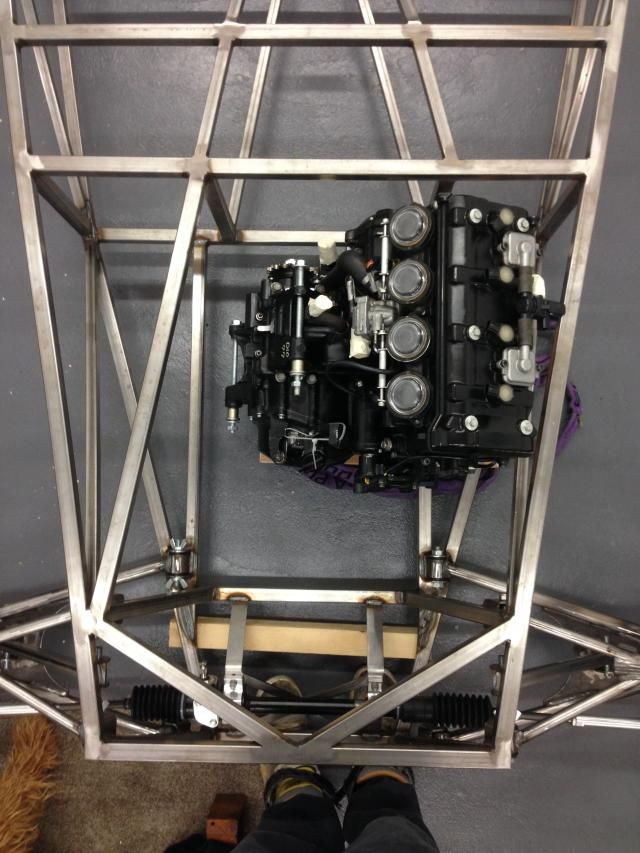
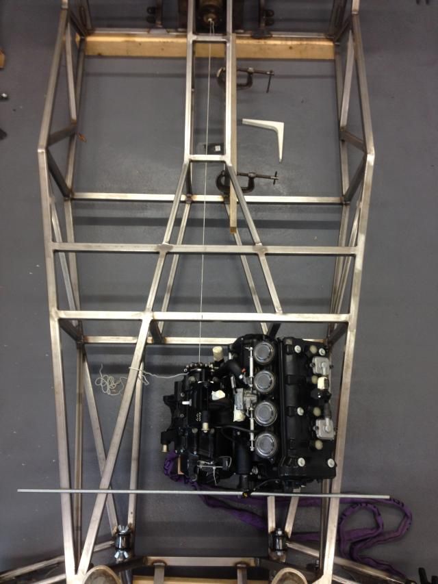
Just been looking at engine position and I'm sort of happy with this current position

Running the engine dead inline it seems to put the output shaft in a good position

If I turn the engine so it's parallel to the outer chassis rail it just skews the output shaft but doesn't improve the position for the prop
And from what I've read it's better for the flanges to be parallel
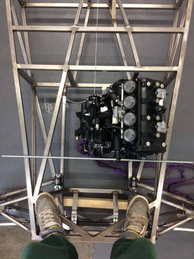


In this position the total prop length would be 1460mm but I could move the engine back 50mm if I moved the passenger footwell upright back

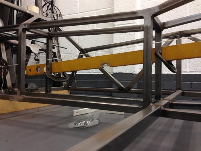
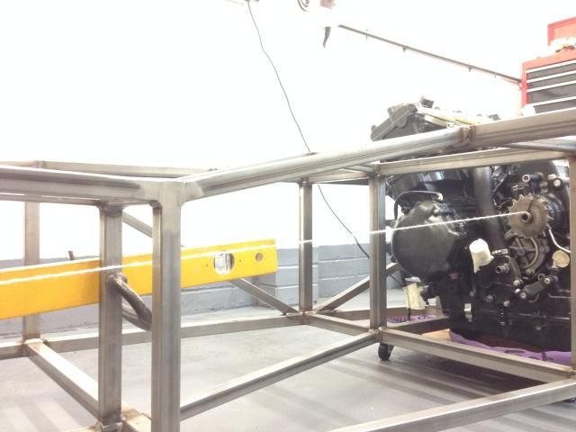
I have strung a ling between and it's at an angle from the horizontal of about 4 deg, I take it I will still need a 2 piece prop with a centre bearing and a slight kink in the centre so the UJ's aren't running straight
Reply With Quote
Reply


Thread Tools
Display Modes

Posting Rules
You may not post new threads
You may not post replies
You may not post attachments
You may not edit your posts

vB code is On
Smilies are On
[IMG] code is On
HTML code is Off
Forum Jump


All times are GMT +1. The time now is 06:49 PM.


Powered by vBulletin® Version 3.6.4
Copyright ©2000 - 2024, Jelsoft Enterprises Ltd.