
|
|
#61
 6th April 2012, 11:26 AM
|
|||
|
|||
|
Quote:
 The rotational movement they are designed to restrict though, is about the propshaft axis not the driveshaft axis. The type of failure Nathan has experienced exibits all the hallmarks of a failure about the driveshaft axis, the cause of which has been encountered by others as poor diff mounting and constraint of movement of the diff nose. This failure is due to poor diff constraint but perhaps due to technician error rather than design. BV  Last edited by Big Vern : 6th April 2012 at 11:35 AM. 
|
|
#62
6th April 2012, 02:08 PM
|
|||
|
|||
|
I think big vern is right, the nose of that diff needs to be well and truly controlled. When you think that a few thousand rpm and a dropped clutch that pinion is trying to climb that crownwheel, that beam across the back is only there to hang the diff unit in place the rest of the forces go to the front mount. i had a quick look round the mx5 fourms and there are dozens of failures with a thousand reasons why, I dont know if I would want something as hit and miss as that an inch from my spine. You could also fabricate a steel brace to run the whole length of the thing and bolt it through the ali bit. It could crack then but at least it would all stay in there.
Bob Edit: An extract from another forum Join Date: Jun 2005 Location: Arizona Posts: 2,007 They do break there very easily. I also think the alloy or casting method somehow makes them excessively brittle too. I had an diff assembly accidentally roll off a floor jack close to the floor and produced the exact same break off with a really minor impact. The exposed cross section's inside looked like classic metal fatigue.
__________________
When The Results Disagree With The Theory: Believe The Results And Invent A New Theory If I had two brains I,d still be a halfwit The cave http://s1116.photobucket.com/user/my...deshow/mancave The build http://www.haynes.co.uk/forums/showthread.php?t=12669 Last edited by robo : 6th April 2012 at 07:03 PM.
|
|
#63
6th April 2012, 04:46 PM
|
|||
|
|||
|
Quote:
Using an the old mx5 engine mount as the front diff mount ain't gonna work. Engine mount is not designed to work in tension! 1.8 mx5 puts out 149N.m torque/5000rpm at the flywheel. =183N.m/4070rpm to the propshaft in 5th gear (0.814:1) Diff ratio= 4.3:1 =787N.m/946rpm at the driveshaft. Thats whats trying to twist the diff out of the chassis  There's no way the tired old engine mount can handle anything like that tension - the rubber will tear away from the steel backing - just try lifting an engine out of the car without undoing an engine and you'll easily see its not up to the job. Nathan, I'm trying to pee on your bonfire, far from it, If only I lived closer I'd come round to see for my self and help out with a solution. There are a few good ideas already coming on here. Do you have a dxf of the chassis in that area I might be able to look at possible solutions a bit easier. BV Last edited by Big Vern : 6th April 2012 at 04:51 PM.
|
|
#64
7th April 2012, 09:28 AM
|
|||
|
|||
|
http://www.solomiata.com/images/RX7pinion.jpg
How about an upgrade to an rx7 diff. No problem with these they have beefed up the whole thing but the prop would be short, the diff mount would end up in the tunnel. Just thoughts Bob
__________________
When The Results Disagree With The Theory: Believe The Results And Invent A New Theory If I had two brains I,d still be a halfwit The cave http://s1116.photobucket.com/user/my...deshow/mancave The build http://www.haynes.co.uk/forums/showthread.php?t=12669
|
|
#65
7th April 2012, 10:06 AM
|
||||
|
||||
|
Quote:
|
|
#66
7th April 2012, 11:42 AM
|
|||
|
|||
|
Quote:
BV
|
|
#67
7th April 2012, 02:03 PM
|
|||
|
|||
|
I have been thinking about mounting the diff in a better way and have read all the posts. I am thinking of mounting it the same way as mazda did with a light weight aluminium beam, using the same bolts spacers etc. Can anyone find a problem with this? I reallise the beam with have to be strong but it will be a little shorter and therefore stronger, with a little thought to the design I think this can be done. the mazda beam was only aluminum anyway.
As for the people who post nothing but unhelpful comments, these people are very shallow minded and are easy to root out. I just look at there previous posts and if most of there comments are unhelpful, I just ignore them. And there posts are usally short.
|
|
#68
7th April 2012, 02:30 PM
|
|||
|
|||
|
Quote:
On the subject of input from certain members I think there are enough intelligent people on here to sift through some of the crap and make their own logical decisions. As far as this diff problem goes its in the interests of the forum members to iron out any bugs to keep things safe. No one wants to go down the road with a diff banging around behind them and a broken prop flailing around a gear tunnel. The mx5 concept is reasonably new and will have the odd issues but nothing insurmountable we have to just keep bouncing ideas about to find that eurika moment.
__________________
When The Results Disagree With The Theory: Believe The Results And Invent A New Theory If I had two brains I,d still be a halfwit The cave http://s1116.photobucket.com/user/my...deshow/mancave The build http://www.haynes.co.uk/forums/showthread.php?t=12669 Last edited by robo : 7th April 2012 at 02:50 PM.
|
|
#69
7th April 2012, 03:34 PM
|
||||
|
||||
|
Quote:
__________________
Albert Haynes Roadster FAQ | Haynes Builder Locations Gallery, build thread in Lithuanian / via Google Translate.
|
|
#70
7th April 2012, 09:35 PM
|
||||
|
||||
|
Hi guys,
I know this is getting a bit of a concern but this is what I have came up with. I decided to make a brace between the top of the diif mountings to tie the two together as if it were a chassis. I've fitted two rubber mounts off the back seat rail one in compression and one in tension at all times (tight bugger to fit)....LOL but seems rigid enough. 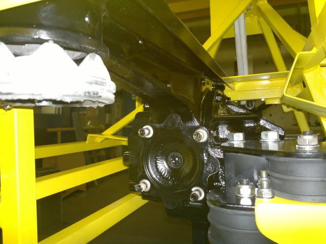 Sorry no triangulation just old plain engineering....LOL 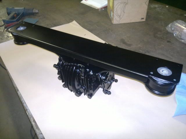 Also fitted lower diff washers as per photo... 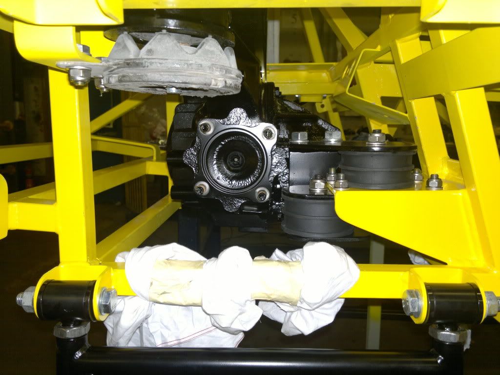 Well if that's not good enough I'm going to get a sore backside as well, because that's what I'm fitting to my car... Have a good weekend Johno..
|
 |
| Thread Tools | |
| Display Modes | |
|
|


 Linear Mode

