
|
|
|
|
#1
 22nd May 2009, 05:57 PM
|
|||
|
|||
|
Quote:
In your design, perhaps you can consider instructions that accomodate different KPI, caster, scrub radius, wheel offset, tire size. Something like a simple geometric drawing that shows where the upper ball joint has to be given all the parameters. Just my 2 cents. Waits eagerly... 
|
|
#2
22nd May 2009, 06:30 PM
|
|||
|
|||
|
I've found a few pics of BMW E30 and E36 differentials for comparison. I believe both chassis were fitted with small (318) and large (325) diffs.
E36 front mount is a single bolt on the lower right side inserted horizontally front to back.  E36 rear mount is a two eared affair integrated into the rear cover. This is a small case judging by the single top bolt in the rear cover. Large cases have 2 bolts.  E30 front mount is four bolts inserted vertically.  E30 rear mount is a single ear on the left side integral with the rear cover. This pic is the small case. Note the single top bolt in the rear cover. 
|
|
#3
22nd May 2009, 10:03 PM
|
|||
|
|||
|
So that adaptor for the front hub is only to extend the height to the upper A arm? Are there other uprights that can be used as like i mentioned before sierra's are pretty hard to find over here.
Another awesome thing to see would be this 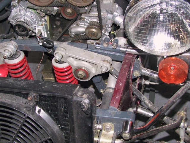 An inboard upright setup, this is the one used by fraser cars in NZ so I am not sure if there are patent issues or anything.
|
|
#4
22nd May 2009, 11:16 PM
|
|||
|
|||
|
Quote:
I'd better explain that, One of the set ups will be better for caster, but I don't know which. Obviously the version with the upright stradling the strut mount would be prefered (double shear) but it might be that the geometry requires the offset version, for example if the balljoint articulation is beyond limits. As I said in my previous post it's an oportunity to decide your own parameters, suspension design is facinating but always a compromise with opposing factors and I think it would be beyond the scope of a build your own type book to do justice to the subject. I'd recommend "competition Car Suspension" by Allan Staniforth (RIP) if you want to get into it. The design would be my best compromise taking into account weight, wheel rates, required roll centres, etc with adjustability built in for people to tinker. Camber adjustment is easy to accomodate if the design uses the Transit drag link end, caster can be adjusted by spacing the bottom and top wishbones (not a lot I'll grant you) KPI is really a function of design, and needs to be set when the upright is made, although camber changes will alter the angle slightly, and scub radius can only be altered, when KPI has been set, by varing wheel offset. It's worth noting that lowering the top wishbones will extend the roll centres almost to infinity, efectively making the set up into a swing axle - think VW Beetle - it'll keep the chassis off the floor but it was abandoned for performance cars in the 1930's! Cheers Chris 
|
 |
| Thread Tools | |
| Display Modes | |
|
|


 )
)


 Hybrid Mode
