
|
|
|
|
#1
 8th August 2009, 12:08 AM
|
||||
|
||||
|
Quote:
__________________
my build pics 
|
|
#2
8th August 2009, 10:25 PM
|
||||
|
||||
|
sorry for being late with the info, had busy day with my family celebrating my mum,s 80th birthday
 measurements for you...... the CP15 plate that is on the outside(offside) is 120mm from the inner edge of TR2 along the TR9 rail, then you have the 40mm width of CP15 then a 60mm gap to the next CP15 plate. i hope this makes sense & hope it helps cheers andy
|
|
#3
8th August 2009, 11:10 PM
|
||||
|
||||
|
Quote:
Thanks!!! that will help me get the steering bits fitted. Ill probably do it on monday as i wont be doing any work tomorrow. Today i made the diff mounting plates, made plates cp10 and fitted them, fitted the diff, and then fitted the other wheel so the whole rear section is rolling  . I then wheel barrowed the chassis outside on the driveway and my neighbours finally realised what i was doing with al the metal and nosie in my garage. . I then wheel barrowed the chassis outside on the driveway and my neighbours finally realised what i was doing with al the metal and nosie in my garage.also, the drive shafts were a tight fit, but nevertheless did fit. I also bought some swarfega from halfords as i was tired of dirty hands and it sucessfully gets rid of oil off my hand(mum was killing me for getting all the walls black ") ) )
__________________
my build pics
|
|
#4
9th August 2009, 03:37 PM
|
||||
|
||||
|
ok, well i tried fitting the steering supports, which seem ok, however im bemused as to how this is all going to work. for a start my steering column doesnt look like it is right, what goes in the cp16 hole to support the coloumn and wheredo you extend it from, it just seems like it wont reach the universal joints at the end of the column the is on the rack as the suspension upright at the front is in the way. I know i have probably not been very clear but hope the pics help. Also where abouts does the yoke go on the coloumn as shown by bonzo a few posts before. It seems that i never had one of those in the first place
  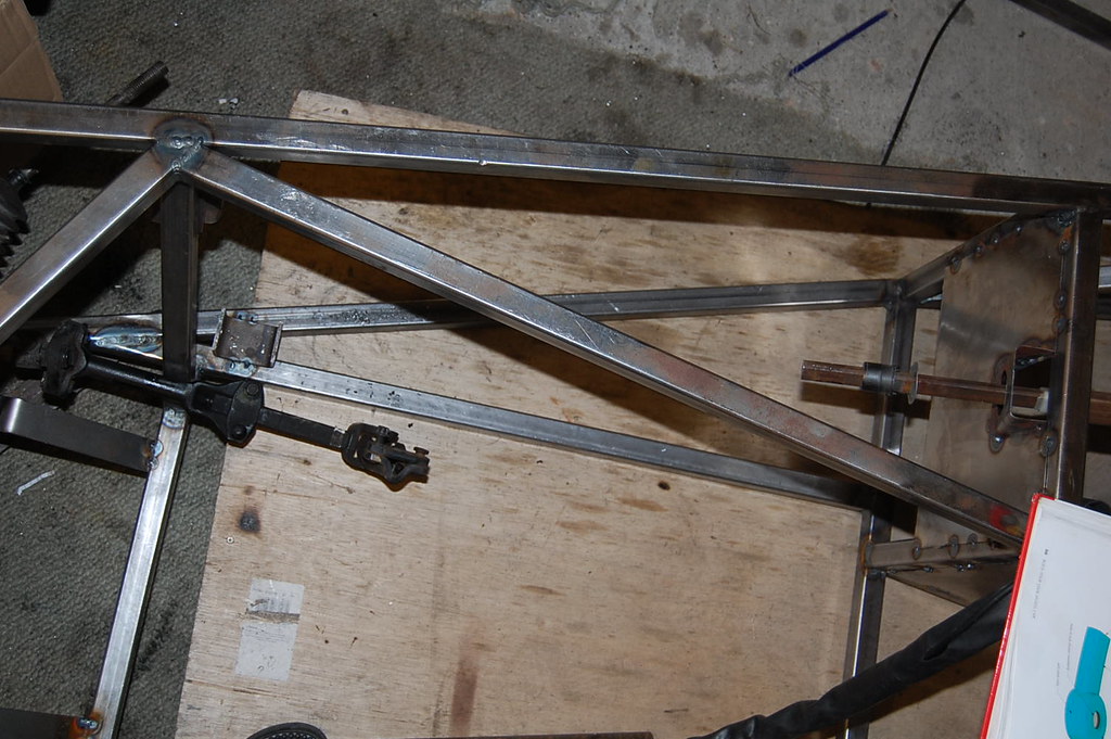 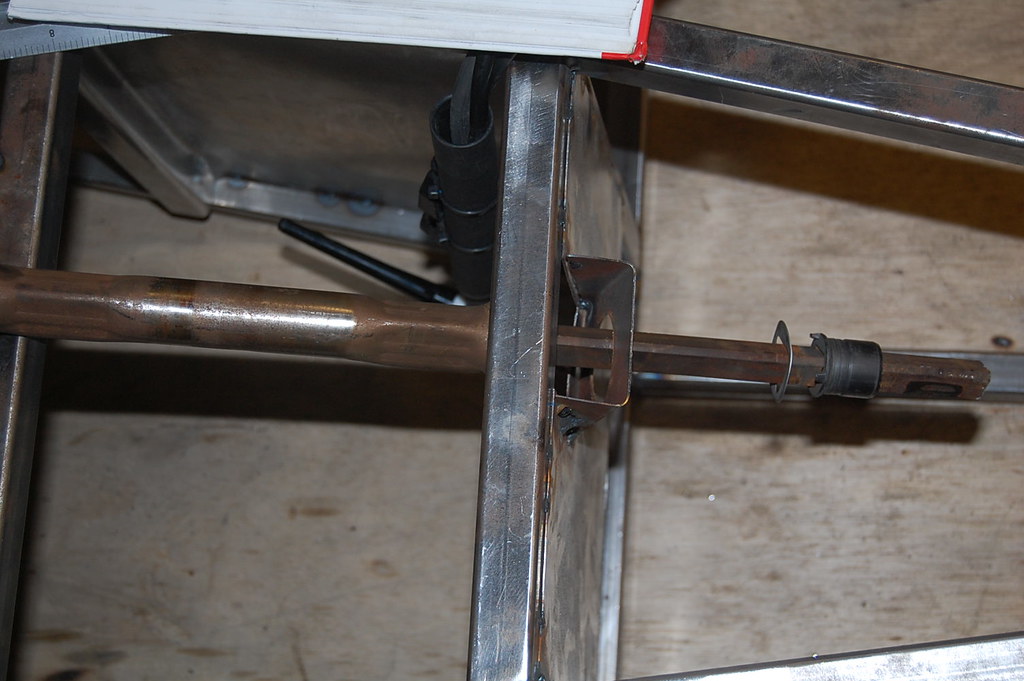 Also, i should say the steering coloumn does sit futher down than what is in the pics, but not my much. THanks
__________________
my build pics Last edited by geeman : 9th August 2009 at 03:48 PM.
|
|
#6
9th August 2009, 04:04 PM
|
||||
|
||||
|
Quote:
(hope im not questioning too much  ) )
__________________
my build pics
|
|
#7
9th August 2009, 04:09 PM
|
||||
|
||||
|
Yeah, mine (which is an adjustable steering column) sits with maybe 100mm past the plate. Then the 1st section of the cut UJ bolts on, then the extension tube (around 400mm I think) then the other half of the UJ, that goes onto the steering rack.

|
|
#8
9th August 2009, 04:12 PM
|
||||
|
||||
|
the little plastic collar needs to go further up the column than how you have it at the mo, this then sits inside the rubber grommet thing that is held in place by the hole in the plate CP16, these are available for £4 off ebay if you haven,t got one.
i have a few pics of how i extended my column down to the coupling on the steering rack, i,ll find them & post them up. and no you are NOT asking too many questions, thats the purpose of the forum, i would be lost without the answers of the lots of questions i,ve asked. cheers andy
|
|
#9
9th August 2009, 04:08 PM
|
||||
|
||||
|
Right, here goes, I'll try to cover it all for you.
The yoke that was posted in one of my pictures bolts to the large holes in the support frame. You'll need to use some largish & thickish penny washers to ensure a good fixing. At the bottom of the yoke there is a hole to take a Pinch bolt. This bolt passes through the two slotted holes on the underside of the steering column. Originally this would have been fitted with an adjustmet lever & plastic fittings to help lock things in place. You will need to fabricate some form of crush tube in order to bolt up tightly. Your steering wheel is a tad too far forward, needs to come back a little. The yoke & pinch bolt assembly should give you more or less the correct position. You need a new steering column bush kit for the large hole in the bulkhead, they are available on ebay for about £5 Once this is fitted the shaft will become quite rigid. Now, this is how I extended my shaft ....OOerrr that sounds a bit rude The section that you currently have connected to the steering rack is the piece I used. It was cut in half, I found some thick wall tube, cut it to the right length. I then welded the part that I cut in half to each end of the tube. As far as I can tell. That part is made of cast steel & welded OK. That said, as a safety feature, I will drill each end through & place a double roll pin in there. My shaft ended up just right & not too close to the chassis or any other components. 
__________________
I am not a complete idiot...........Some of the parts are missing !! Ronnie www.roadster-builders.co.uk
|
|
#10
9th August 2009, 04:15 PM
|
||||
|
||||
|
Quote:
as alot of what you said seems what would be fairly obvious, but... nothings ever easy
__________________
my build pics
|
 |
| Thread Tools | |
| Display Modes | |
|
|


 Hybrid Mode
