
|
|
|
|
#2
 9th April 2010, 02:17 PM
|
||||
|
||||
|
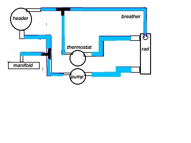
I've sketched out an overhead view of how my pump / thermostat housing is on the engine. The pre-thermostat outlet on the housing, I assume should go into the small outlet on the pump?
Now I also assume that the header tank sits on this local loop (red) otherwise any coolant added wouldn't reach the engine cos of the closed thermostat when cold. Any more advice on all this would be appreciated.  
|
|
#3
9th April 2010, 07:20 PM
|
||||
|
||||
|
Dezee,
thats basically what I've done, if I'm reading it right the red lines would be the take off and return for the original car heater giving you a flow of coolant all the time. Just stick a T piece in to connect the expansion tank. I take it there are vent lines as well. Hope thats helpful.
|
|
#4
10th April 2010, 08:48 AM
|
|||
|
|||
|
Need to hi-jack this thread here.
I'm unsure where I should connect the small water pipe coming from the front of the CVH head, that's the one on the exhaust side. Is it just a vent? I'm using a FWD thermostat housing on the back of the head so if it's a vent is it required as the thermostat will vent there. J
|
|
#5
10th April 2010, 03:27 PM
|
|||
|
|||
|
Quote:
|
 |
| Thread Tools | |
| Display Modes | |
|
|


 Hybrid Mode
