
|
|
|
|
#1
 18th August 2011, 08:36 AM
|
||||
|
||||
|
Problem is it's a triangle shape at both ends of the column so to speak so I've got bendable coupling at the top like you have in http://www.haynes.co.uk/forums/attac...9&d=1313167124 but then i have a similar coupling at the bottom at the rack end (which has the escort spline on it). Also your chassis appears a bit different (must be because of being a 442e) in the front as your diagonals that can be seen in http://www.haynes.co.uk/forums/attac...8&d=1313167107 sit much closer to the outside of the chassis compared to the book spec ones. I do like how your rack mount looks though as it's kind of what I had in mind in terms of changing the height/angle of the rack slightly to clear the diagonals better.

|
|
#2
18th August 2011, 10:41 AM
|
||||
|
||||
|
Post some pictures of your chassis / steering setup so we can have a look and see what the problem is.
__________________
http://s831.photobucket.com/user/dav...ter%20Pictures OTR 01/05/14 - 1.6 CVH, Type 9, Bike Carbs, Megajolt
|
|
#3
18th August 2011, 11:26 AM
|
||||
|
||||
|
Will do later when I get home. I've cut the rack mount back out now & will have to remake it. I made it originally to book spec not realizing there was something in the amended one in the annoucements but with my book being fairly new, I would have though it would include these changes? From what I've gleaned from reading around, the arms of the rack should be level with where they'll connect onto the hubs and not go at an upward/downard angle if you look at it from the front of the car. However, should it also be a straight line from the rack out to where it connects onto the hub?
|
|
#4
18th August 2011, 12:43 PM
|
||||
|
||||
|
I,ve been following this thread & am a little confused to whats causing the problems
 as dave has suggested photo,s would be good  With regard the column extension going past the diagonal...to solve this I made my extension "stepped" so that as it passes that diagonal it gives plenty of clearance . I,ve used a group 4 coupling at the rack end & then used the triangular Ford part at the upper part of the column extension to where it joins the column that goes thru the bulkhead ( not sure if that makes sense  ) )cheers andy
|
|
#5
18th August 2011, 01:09 PM
|
||||
|
||||
|
I guess in a nut shell I'm stuck on how to position my rack so it doesn't foul on the diagonal and I don't end up with bad bump steer? Not sure what you mean about a stepped extension, could you post a pic of it as it may be the solution I need
For the coupling, it sounds like I may have got the wrong one.. I'm guessing you've used one of these http://www.rallydesign.co.uk/product...oducts_id=7333. I understand that one end will have a spline that goes onto the rack, but what I don't get is how you connect the extension onto this as the end of my extension has a triangle shape? (hence why I used the sierra->escort coupling).
|
|
#6
18th August 2011, 01:18 PM
|
||||
|
||||
|
Attached are a couple od pictures of my steering.
The first is the upper section of the steering columns. The triangular part is uppermost in the pictures. 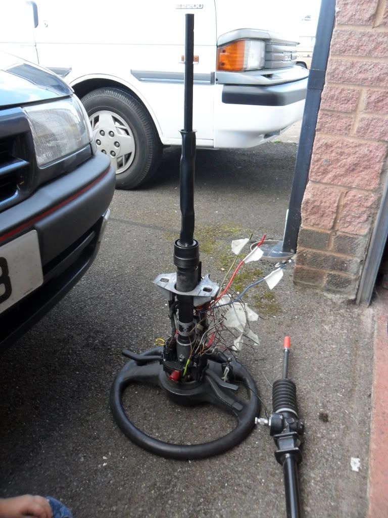 The next picture shows the cut and extended lower section of the standard Sierra column. The end that fits the triangular section is uppermost with the splied coulping at the other end. The bit of tube I used to extend it was a piece of seamless tube left over from the lower wishbones. It gets close to the diagonal, 3-4mm. But it doesn't touch and that is all that matters. 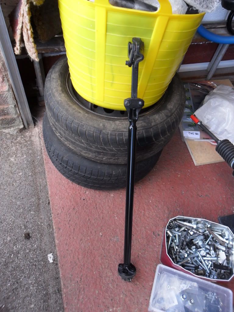
__________________
http://s831.photobucket.com/user/dav...ter%20Pictures OTR 01/05/14 - 1.6 CVH, Type 9, Bike Carbs, Megajolt
|
|
#7
18th August 2011, 01:25 PM
|
||||
|
||||
|
That's pretty much how I did mine dave, the only thing that I changed was the coupling on the end with the spline as the spline off mine was too big to fit onto the escort rack. hence why I bought the sierra->escort coupling off rally design. but i think the rack position must have been wrong somehow to cause the extension and coupling with the spline fouling on the diagonal?
|
|
#8
18th August 2011, 01:24 PM
|
||||
|
||||
|
Dave beat me too it, nice one Dave.
Mines the same as Daves at the upper end ( triangular part ) but my lower end of the extension doesn,t have the rubber coupling as i,ve changed mine to the group4 coupling. Yes , thats the coupling i,ve used in conjunction with a splined shaft from Rally Design. so imagine the order of placement as this ...... rack....group4 coupling....splined shaft ( fits the coupling splines ).....thick walled tubing......once passed the diagonal U2 ......more slightly thicker walled tubing ( this is my meaning of stepped )......the triangular Ford part with the rubber coupling cut off......then the triangular clamp end fits onto the collapsible part of the column that goes thru the bulkhead.I,ll try and find a pic and post it up. When you say "diagonal" ... I presume you mean part "U2" ? The placement of the rack itself shouldn,t cause a problem if parts CP19,20 & 21 have been welded into the correct postion. cheers andy Last edited by HandyAndy : 18th August 2011 at 01:27 PM. Reason: extra info with ref Daves pics
|
 |
| Thread Tools | |
| Display Modes | |
|
|


 Hybrid Mode
